HercuLeS 1.0 reference manual
| Date: | 2013-06-29 |
|---|---|
| Author: | Nikolaos Kavvadias <nkavvadias@ajaxcompilers.com> |
| Email: | info@ajaxcompilers.com |
| Revision: | 0.0.1 (2012-05-10), 0.0.2 (2013-05-29) |
| Web site: | http://www.ajaxcompilers.com |
| Copyright: | Nikolaos Kavvadias (C) 2009, 2010, 2011, 2012, 2013 |
HercuLeS, the constellation.
Contents
- 1 HercuLeS basics
- 2 More on HercuLeS
- 3 gimple2nac
- 3.1 Introduction
- 3.2 Target audience
- 3.3 Issues with tagged GIMPLE
- 3.3.1 Losing the original semantics of the source program
- 3.3.2 Inconsistency in handling labels
- 3.3.3 Destroyed interfaces
- 3.3.4 Pointer expressions
- 3.3.5 Function calls
- 3.3.6 Inconsistency in array initialization sequences
- 3.3.7 Inconsistency of the tagged GIMPLE format
- 3.3.8 Lack of bit-accurate semantics
- 3.4 Final notes on GIMPLE
- 4 The NAC programming language
- 5 C coding style
- 6 Limitations of the free web interface
- 7 FSMDs
- 8 The HercuLeS GUI
1 HercuLeS basics
1.1 Introduction
HercuLeS is a High-level synthesis tool that automatically generates RTL VHDL for non-programmable hardware. HercuLeS translates programs in NAC (a bit-accurate typed-assembly language) to extended FSMDs (Finite-State Machines with Datapath) in VHDL. HercuLeS can also be used for direct synthesis of ANSI C code to VHDL with the help of a prototype translator from GIMPLE which is GCC's new intermediate representation to NAC.
Internally, HercuLeS comprises of two main components: a frontend (nac2cdfg) and a graph-based backend (cdfg2hdl):
- nac2cdfg
- translator from NAC (N-Address Code) IR, to flat CDFGs represented in Graphviz
- cdfg2hdl
- the actual HLS tool for automatic FSMD hardware and self-checking testbench generation from Graphviz files to VHDL
HercuLeS also has an additional ANSI C backend, allowing comparison of NAC programs to reference ANSI C application code and the rapid prototyping of applications (VHDL simulation can be slow depending on design complexity, input data and the simulator used).
VHDL code generated by HercuLeS can be simulated with GHDL and the industry- standard Modelsim. It is possible to generate VHDL using either the Synopsys packages (the "old" de-facto standard) or the official IEEE library packages. HercuLeS supports fixed-point arithmetic via sfixed and ufixed vectors as defined by the VHDL-2008 fixed-point arithmetic packages. For this option, HercuLeS should be notified (via command-line option) to use the IEEE packages.
1.2 Conceptual flow
The basic steps in the HercuLeS flow are shown in Fig. hercules-overview. C code is passed to GCC for GIMPLE dump generation, optionally following an external source-level optimizer. Textual GIMPLE is then processed by gimple2nac; alternatively the user could directly supply a NAC translation unit (TU).
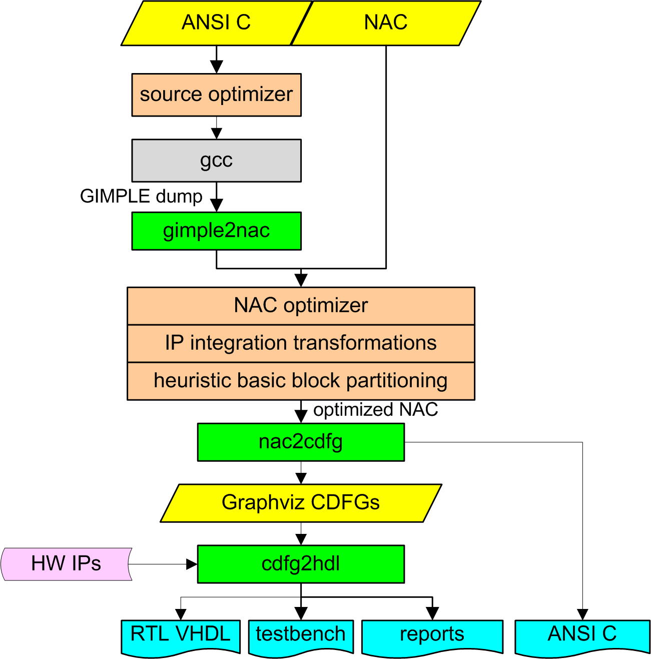
The HercuLeS flow.
Various optimizations have been applied at the NAC level; peephole transformations, if-conversion, and function call insertion to enable IP integration. Heuristic basic block partitioning avoids the introduction of excessive critical paths due to operation chaining.
The core of HercuLeS comprises of a frontend (nac2cdfg) and a graph-based backend (cdfg2hdl). nac2cdfg is a translator from NAC to flat CDFGs represented in Graphviz. cdfg2hdl is the actual synthesis kernel for automatic FSMD hardware and self-checking testbench generation from Graphviz CDFGs to VHDL.
nac2cdfg is used for parsing, analysis and CDFG extraction from NAC programs. SSA form is supported based on minimal generation algorithms. Data flow analysis uses on-demand graph reachability checking.
cdfg2hdl maps CDFGs to an extended FSMD MoC (Model of Computation). For scheduling operations to specific states, either sequential or control- aware ASAP scheduling can be used. ASAP can be combined with fast operation chaining for better state workload balancing.
The generated FSMDs are generalized FSMs introducing embedded actions, with: a) support of array input, output and streaming I/O ports, b) communication with embedded block and distributed LUT memories, c) latency-insensitive local interface between caller and callee FSMDs, and d) interfacing to external IP blocks.
An additional ANSI C backend allows for rapid algorithm prototyping and NAC verification. VHDL code can be simulated with GHDL and Modelsim.
1.3 Overview
The current features of HercuLeS include:
- Multiple subprograms (procedures) and procedure calls
- GIMPLE-to-NAC prototype frontend
- NAC (N-address code) parsing and semantic analysis
- Support for SSA form IR (in-to-SSA and out-of-SSA translations) based on Appel's "really-crude" method and Aycock-Horspool's iteratively eliminating algorithms for minimal SSA
- Translation of NAC input programs to Graphviz CDFGs
- CDFG (organized as Graphviz graphs) parsing and semantic analysis
- Support of:
- multi-precision integer (std_logic_vector) and fixed-point (sfixed, ufixed) arithmetic
- basic low-level IR operators
- extended FSMD model of computation
- "scalar" and "streamed" (emitting a series of result values over time) outputs
- single-dimensional arrays (Multidimensional arrays can always be reduced to single-dimensional ones via matrix flattening)
- parameter passing through array procedure arguments
- automatic inference of block-RAM storage (for FPGAs)
- Scheduling engines
- Sequential scheduling
- Control-aware ASAP scheduling
- Control-aware ASAP scheduling with operation chaining (2x-4x better performance)
- Optimizations
- Source-to-source C code optimizer (preliminary)
- Integration of constant multiplication and division (kdiv) optimizations
- Integration of peephole-based optimizer
- Data flow analysis (conservative custom method using on-demand graph reachability checks)
- Interface to a graph matching (graph and subgraph isomorphism) engine
- Various APIs:
- Common abstract data types
- Combinatorial objects generator
- Interval arithmetic
- Data flow analysis
- Simple graphs (undirected and directed)
- Attributed graphs (undirected and directed)
- Generators
- VHDL design code (FSMD datapath and control)
- Self-checking VHDL testbench
- Various script files (Makefiles, shell scripts) for GHDL/Modelsim simulations
- Generation of Makefiles and scripts for running logic synthesis tools
- Hardware operator library
- Configurable multipliers
- Logarithm functions
- Variable shifters
- Dividers and modulo extractors
- TODO list
- Multi-port memory synthesis
- Access to global data from any procedure. Currently only the "root" procedure can access globals
- Support of dynamically allocated data
- Support of record data types (e.g. ANSI C structs)
- Register optimization
- List scheduling with operation chaining optimizations
- Graph-based optimization engine
- Enhanced data flow analysis
- Recursive procedure support [Currently supported in the C backend]
1.4 Quick-start guide to the HercuLeS web interface
The purpose of this text is to provide a quick-start guide to using the HercuLeS high-level synthesis tool through a web interface. This version of HercuLeS does not provide access to certain features such as arithmetic and loop-oriented optimizers.
Minimal requirements:
- Linux or Windows XP/Cygwin (a POSIX environment offering bash and common UNIX utilities).
- GHDL or Modelsim.
Visit the HercuLeS web interface.
Unzip http://www.nkavvadias.com/hercules/hercules-contrib-vhdl.zip to a local directory, e.g. C:\hercules\contrib
Create an empty directory, e.g. C:\hercules\tests
Either select the supplied (already pasted) example of the "fact" (factorial) function or copy and paste your own. Download http://www.nkavvadias.com/hercules/small-examples.zip for a few ANSI C and NAC (generic assembly) code samples.
NOTES:
- In order to use the automatically-generated testbench, add a main() function to your code, enclosed by the preprocessor directive:
#ifdef TEST
#endif
- In addition, it is expected that the main() function generates input and reference output samples in hexadecimal format and in separate columns. A proper main() would generate such samples in a file named fact_test_data.txt (for the fact example).
- Standard C library includes should be also enclosed by the aforementioned directive.
- Read Section 5 of http://www.nkavvadias.com/hercules/hercules-web-guide.html for a short guide on ANSI C code style and limitations (WIP).
- On the web interface page, give the name of the top-level function/procedure in your test code in the corresponding box. For instance, in the supplied example this is: fact
- In the following box, give your personal email, e.g. nikolaos.kavvadias@gmail.com Unless you provide an email address, it is not possible to receive generated files from HercuLeS.
- Choose implementation options from the menu or keep the defaults (where
multiple options exist, the first option is the default):
- Input in "C" or "NAC" language.
- Scheduling policy: sequential, ASAP or ASAP with chaining (could result in faster hardware).
- [Optional] Select visualization options, in case you want to receive the CDFG and CFG visualizations of all processed functions/procedures.
- Select the generation of simulation scripts for either "GHDL" or "Modelsim".
- [Optional] Force the usage of block RAMs for ROM/RAM memory, when applicable.
- Hit "Submit".
- In a few minutes (depending on your input), you will receive the generated files in your mailbox, archived in .tar.gz format. Extract these files accordingly to a new subdirectory inside C:\hercules\tests For the case of the fact example this would be: C:\hercules\tests\fact
- From the command line (e.g. cygwin bash), change directory to C:\hercules\tests\fact and run the generated script that invokes the simulation: ./fact.sh
- A successful simulation ends with an assertion reporting: "Failure: NONE". Examine the diagnostic output in fact_alg_test_results.txt to obtain the number of target hardware cycles needed to process each sample. A simulation waveform is generated in file fact_fsmd.vcd. Your design files are generated in VHDL (.vhd) using the IEEE libraries; for the fact example this is: fact.vhd. The automatically-generated testbench is named after the top-level function, e.g. fact_tb.vhd
2 More on HercuLeS
2.1 How it works
The following figure gives an internal view to the process flow of HercuLeS.
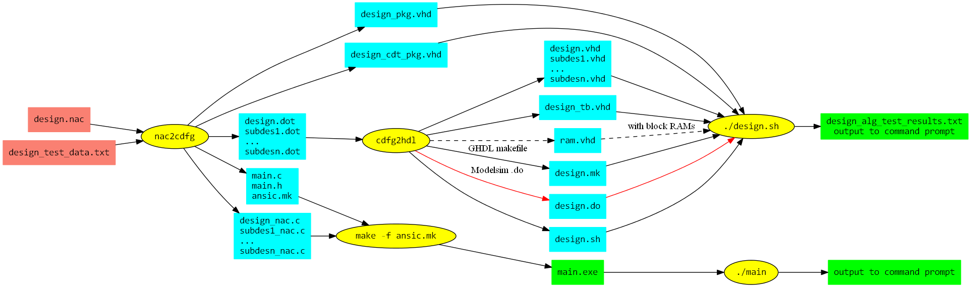
How HercuLeS works.
The user of HercuLeS must provide two input files:
- design.nac: A NAC program translation unit providing the entire application. The root procedure must be named "design".
- design_test_data.txt: Input/output reference values for use by the automatically-generated testbench
Then, nac2cdfg generates several files:
- design.dot, subdes1.dot, ..., subdesn.dot: The Graphviz CDFGs for the root procedure and all other procedures in the NAC program.
- main.c, main.h, ansic.mk: Files generated for running an ANSI C simulation. ansic.mk is an automatically-generated Makefile.
- design_nac.c, subdes1_nac.c, ..., subdesn_nac.c: ANSI C backend files providing C implementations of all procedures in the translation unit, generated directly from NAC. They are used in the C simulations.
- design_pkg.vhd: VHDL package incorporating the components for all NAC procedures.
- design_cdt_pkg.vhd: VHDL package incorporating definitions of compound data types (arrays).
Following this, there exist two possible flows; one for the generation and simulation of synthesizable RTL VHDL for the NAC program, and one for a C simulation.
The C simulation flow proceeds by invoking the ansic.mk makefile by running:
make -f ansic.mk
from the command line. This produces a main.exe executable specification (e.g. on Windows/Cygwin). Then, the executable is run:
./main
and output is produced at the command prompt.
The VHDL flow involves processing all CDFG (.dot) files by cdfg2hdl, the actual backend tool of HercuLeS. cdfg2hdl generates several files:
- design.vhd, subdes1.vhd, ..., subdesn.vhd: Synthesizable RTL VHDL for the root procedure and all other procedures in the NAC program.
- ram.vhd: VHDL model of a dual-port synchronous read RAM for block RAM inference. It is only used if block RAM mapping is enabled.
- design_tb.vhd: The automatically-generated self-checking testbench.
- design.mk: Makefile for running a GHDL simulation.
- design.do: Modelsim do macro file for running a Modelsim simulation.
- design.sh: Bash shell script initiating either a GHDL or Modelsim simulation.
Finally, the design.sh script is run from the command line:
./design.sh
This produces a text file (design_alg_test_results.txt) providing diagnostic output from a simulation run. Output to the command prompt for any internal program variable, procedure argument, etc can be produced by using the "print" NAC operation. A "print" is mapped to a VHDL "assert" construct or a C standard library "printf".
Also, a VCD (design_fsmd.vcd) or GHW (design_fsmd.ghw) waveform file can be generated for viewing with GTKwave. Windows binaries for GTKwave can be found at http://www.dspia.com/gtkwave.html.
2.2 nac2cdfg
The usage of the nac2cdfg is as follows:
nac2cdfg [options] input.nac
where options is one or more of the following:
- -d:
- Enable debug output.
- -force-data-types:
- Force predefined data types as given in NAC code. Essentially disables the effect both interval analysis and the alternative of using the unknown data type na.
- -permissive:
- Allows non-strict forms and macrostatements of the NAC programming language.
- -ssa:
- Internal construction of SSA (Static Single Assignment) form.
- -pseudo-ssa:
- Internal construction of local SSA-like form.
- -use-appel:
- Enables SSA construction using Appel's algorithm.
- -use-aycockhorspool:
- Enables SSA construction using the Aycock-Horspool algorithm (default).
- -opt-spbb:
- Enables optimization 3 as discussed in the Aycock-Horspool paper, which omits generating phi statements for single-predecessor BBs. Supported only with -use-appel and -keep-ssa.
- -keep-ssa:
- Does not perform out-of-SSA conversion and thus keeps PHI statements in the generated CDFGs.
- -limit-nacs:
- Limits the number of NACs in a translation unit to NAC_LIMIT (about 25).
- -emit-nac:
- Emit the equivalent NAC program after processing (including SSA conversion, if enabled).
- -emit-ansic:
- Emit the equivalent ANSI C program after processing (including SSA conversion, if enabled).
- -emit-cfg:
- Generate the Graphviz representations for all procedure CFGs.
- -dump-varnum-nac:
- Dump the equivalent NAC program after SSA variable numbering.
- -dump-phiins-nac:
- Dump the equivalent NAC program after SSA PHI insertion.
- -dump-phimin-nac:
- Dump the equivalent NAC program after SSA PHI minimization.
- -dump-phielm-nac:
- Dump the equivalent NAC program after SSA PHI elimination.
- -dump-simdce-nac:
- Dump the equivalent NAC program after post-SSA dead code elimination.
- -dump-tgf:
- Dump TGF (Trivial Graph Format) representations of program information.
- -dump-arg:
- Dump ARG (attributed relational graph) representations of program information.
- -dump-grh:
- Dump simple edge-list representations of program information.
- -dump-poset:
- Dump poset (.p) file representations of program information.
2.3 cdfg2hdl
The usage of the cdfg2hdl is as follows:
cdfg2hdl [options] input.dot
where options is one or more of the following:
- -d:
- Enable debug output (nothing yet).
- -sched-<mode>:
- Perform scheduling on predefined acyclic regions. Valid options for <mode>: {sequential, asap, naive}.
- -mpint:
- Use multiple-precision arithmetic as implemented by the public domain fgmp library.
- -streaming:
- Generate code for hardware units with streaming output(s), generating a sequence of values.
- -vhd2vl:
- Generate code more friendly to the "vhd2vl" tool.
- -use-rising-edge:
- Use calls to rising_edge for clock event detection.
- -use-component-pkg:
- Generate a package "use" for system-wide components.
- -ghw:
- Generate a GHDL Waveform file (.ghw) after simulation.
- -vcd:
- Generate a VCD waveform file (.vcd) after simulation.
- -read-through, -read-first:
- Specify the mode for block RAM synchronous reads (default: read-first).
- -blockmem:
- Generate embedded block memories via inference.
- -synopsys:
- Use the de-facto Synopsys IEEE library in the generated design code (default).
- -ieee:
- Use the normative IEEE library in the generated design code.
- -hw-phis:
- Generate hardware for direct support of phi statements.
- -fxp-trn-wrap:
- Support for fixed-point arithmetic with truncation (quantization mode) and wrapping (overflow mode). This is the default option.
- -fxp-trn-sat:
- Support for fixed-point arithmetic with truncation (quantization mode) and saturation (overflow mode).
- -fxp-rnd-wrap:
- Support for fixed-point arithmetic with rounding (quantization mode) and wrapping (overflow mode).
- -fxp-rnd-sat:
- Support for fixed-point arithmetic with rounding (quantization mode) and saturation (overflow mode).
- -ghdl:
- Generate support files for GHDL simulation (default).
- -mti:
- Generate support files for Modelsim simulation.
- -quick-abort:
- Abort simulation immediately following the first error.
2.3.1 CDFG construction
A novel, fast CDFG construction algorithm has been devised for both SSA and non-SSA NAC forms producing flat CDFGs as Graphviz files. A CDFG symbol table item is a node (operation, procedure call, globalvar, or constant) or edge (localvar) with user-defined attributes: the unique name, label and data type specification; node and edge type enumeration; respective order of incoming or outgoing edges; input/output argument order of a node and basic block index. Further attributes can be defined, e.g. for scheduling bookkeeping.
This approach is unique since it focuses on building the CDFG symbol table (st) from which the associated graph (cdfg) is constructed as one possible of many facets. It naturally supports loop-carried dependencies and array accesses.
// CDFG construction algorithm accepting BASIL input.
NACtoCDFG()
  input List BASILs, List variables, List labels, Graph cfg;
  output SymbolTable st, Graph cdfg;
begin
  Insert constant, input/output arguments and globalvar
  operand nodes to st;
  Insert operation nodes;
  Insert incoming {global/constant/input, operation} and
  outgoing {operation, global/output} edges;
  Add control-dependence edges among operation nodes;
  Add data-dependence edges among operation nodes,
  extract loop-carried dependencies via cfg-reachability;
  Generate cdfg from st;
end
3 gimple2nac
gimple2nac translates GIMPLE dumps to NAC TUs, which presents challenges. Currently, GIMPLE loses source semantics such as global scope variables. A workaround for some cases is the definition of static variables in the original source. Other issues involve: format inconsistencies following different optimization passes, handling labels and array initialization sequences, destroyed interfaces and lack of bit-accuracy. Some of these problems are targeted by a GCC rewrite [GIMPLEbe] that will allow emitting GIMPLE as a target language.
3.1 Introduction
GIMPLE is the machine-independent intermediate representation used in modern GCC releases (post version 4.0). While the GIMPLE API for code generation and manipulation has matured over time, the corresponding textual representation is yet to be in a stable form. This issue hampers many serious efforts for code generation from and to GIMPLE.
Good candidates for the textual representation seem to have been in play for some time. The wiki site http://gcc.gnu.org/wiki/GIMPLE sketches the textual IR that is expected to be implemented by the GIMPLE frontend and backend (both under development). Another case of a textual GIMPLE are the formats generated as a GIMPLE dumps. We distinguish here two formats: the format in *.t004.gimple files (tagged GIMPLE) and the one e.g. in *.t140.optimized files (GIMPLE-C). Both formats express the low-level GIMPLE representation, which is closer to classic three-address code than high-level GIMPLE; the latter is closer to the GENERIC AST representation. An extended form of GIMPLE dumps are expected to be established as the GIMPLE language semantics.
For reference tagged GIMPLE is generated by the command-line option:
-fdump-tree-all-raw
while GIMPLE-C is generated by:
-fdump-tree-all and -fdump-tree-gimple
the latter only emitting the *.t004.gimple file.
The rest of this document discusses open issues with the textual GIMPLE IRs, focusing on the tagged GIMPLE format. It will not cover extended semantics issues that are covered much better at http://gcc.gnu.org/wiki/GIMPLEFrontEnd
3.2 Target audience
This section is expected to be of interest to compiler/translator implementors using GIMPLE as either a source or target language.
3.3 Issues with tagged GIMPLE
Here follows a listing of some issues that can be identified with using tagged GIMPLE. Most of them apply to the GIMPLE-C format as well.
3.3.1 Losing the original semantics of the source program
One such example is the omission of emitting global variables. A workaround for some cases is the definition of static variables in the original source. This approach provides only specific file/translation unit scope to globals but it is not certain whether the extern specifier is handled properly for referencing these globals from external scope.
3.3.2 Inconsistency in handling labels
Automatically generated labels (by the gimplifier) and labels defined in the source program are represented differently. The first category are enclosed in single wedges < > while the later are explicitly defined and are used without wedges.
For example, this is the definition of an automatically generated label:
gimple_label <<D.1983>>
while the following is the (redundant) definition:
void V1 = <<< error >>>; ... ``gimple_label <V1>
and the use of a source label:
gimple_cond <eq_expr, D.1985, 1, V5, <D.1986>>
3.3.3 Destroyed interfaces
Function interfaces are not maintained appropriately since the original argument types in a function definition may be replaced. This is the case with array arguments (with static sizes) in the definition of non-root procedures.
Here follows an example. This is the a partial view of the source program:
void evalcoins(int n, int amount, int C[], int *ncoins, int D[])
{
  ...
}

void coins(int n_eurocents, int *n_coins_used)
{
  int C_euro[15], D_euro[15];
  ...
  evalcoins(15, n_eurocents, C_euro, &n_items, D_euro);
  ...
}

However, this is the tagged GIMPLE form of the same program:
evalcoins (int n, int amount, int * C, int * ncoins, int * D)
gimple_bind <
  ...
>

coins (int n_eurocents, int * n_coins_used)
gimple_bind <
  int C_euro[15];
  int D_euro[15];
  ...
  gimple_call <evalcoins, NULL, 15, n_eurocents,
               &C_euro[0], &n_items, &D_euro[0]>
  ...
>
3.3.4 Pointer expressions
Low-level GIMPLE (tagged and GIMPLE-C) use two basic specific operations for dealing with pointer expressions and indirect references, the pointer_plus_expr and indirect_ref.
A pointer_plus_expr in tagged GIMPLE appears as follows:
gimple_assign<pointer_plus_expr, D.1986, D, D.1985>
where D is an array, D.1985 a temporary int variable and D.1986 a temporary variable defined as pointer to int.
The same in GIMPLE-C is the following:
D.1986 = D + D.1985
This operation adds the offset determined by D.1985 to the base address of array D, expressed as D. Pointer D.1986 then can be used for intexing the array.
A typical idiom in generated GIMPLE suggests that pointer_plus_expr is followed by an indirect_ref. The indirect reference is used to access the array and loading the contents of a memory position to a variable.
An indirect_ref in tagged GIMPLE appears as follows:
gimple_assign<indirect_ref, D.1987, *D.1986, NULL>
and the same in GIMPLE-C is:
D.1987 = *D.1986;
In order to avoid a thorough pointer analysis for establishing that D.1986 points to the contents of array D, typical data-dependence analysis can be used to trace that D is the referenced entity by D.1986.
3.3.5 Function calls
Function calls are represented by gimple_call in tagged GIMPLE. Due to the issue 3 (Destroyed interfaces), in some cases calls-by-reference appear when not really needed. This refers to the simulated call-by-reference available in the C programming language, and not the actual kind that can be found, e.g. in Perl.
For example the following call is by-reference:
gimple_call <..., &C_euro[0],...>
making use of the address of the first element of C_euro (the base address).
With interfaces kept unchanged, the following would suffice:
gimple_call <..., C_euro, ...>
3.3.6 Inconsistency in array initialization sequences
An array can be initialized either by a literal initialization list or by emitting a sequence of operations for initializing its contents. From a black-box point of view, it seems that the gimplifier arbitrarily chooses which approach to follow.
For example, in our example, the C_euro is initialized via explicit operations:
gimple_assign <integer_cst, C_euro[0], 1, NULL>
gimple_assign <integer_cst, C_euro[1], 2, NULL>
gimple_assign <integer_cst, C_euro[2], 5, NULL>
gimple_assign <integer_cst, C_euro[3], 10, NULL>
gimple_assign <integer_cst, C_euro[4], 20, NULL>
gimple_assign <integer_cst, C_euro[5], 50, NULL>
gimple_assign <integer_cst, C_euro[6], 100, NULL>
gimple_assign <integer_cst, C_euro[7], 200, NULL>
gimple_assign <integer_cst, C_euro[8], 500, NULL>
gimple_assign <integer_cst, C_euro[9], 1000, NULL>
gimple_assign <integer_cst, C_euro[10], 2000, NULL>
gimple_assign <integer_cst, C_euro[11], 5000, NULL>
gimple_assign <integer_cst, C_euro[12], 10000, NULL>
gimple_assign <integer_cst, C_euro[13], 20000, NULL>
gimple_assign <integer_cst, C_euro[14], 50000, NULL>

It is not clear why an initialization list is not used:
int C_euro[15] = {1, 2, 5, 10, 20, 50,
                  100, 200, 500, 1000, 2000, 5000,
                  10000, 20000, 50000};
Automatically generated labels (by the gimplifier) and labels defined in the source program are represented differently. The first category are enclosed in single wedges < > while the later are explicitly defined and are used without wedges.
For example, this is the definition of an automatically generated label:
gimple_label <<D.1983>>
while the following is the (redundant) definition:
void V1 = <<< error >>>; ... ``gimple_label <V1>
and the use of a source label:
gimple_cond <eq_expr, D.1985, 1, V5, <D.1986>>
3.3.7 Inconsistency of the tagged GIMPLE format
As discussed in the introduction, the tagged GIMPLE format uses alternate syntax for the unoptimized (*.t004.gimple) and certain optimized (e.g. *.t140.gimple) intermediate code dumps. It would be clearer if a single convention throughout all GIMPLE dumps.
3.3.8 Lack of bit-accurate semantics
The availability of bit-accurate data types is an interesting asset of modern compiler infrastructures such as LLVM: http://www.llvm.org. LLVM uses the LLVM bitcode IR which adheres to such semantics. On the other side, GCC GIMPLE might be too closely coupled with C-like semantics. Especially, implementors of non-conventional backend architectures (e.g. developers of hardware compilers) would be interested in a form of GIMPLE with bit-accurate types.
For example, the following would denote a 14-bit unsigned integer and a 8.16 signed fixed-point representation, respectively.
- u14
- q8.16s
3.4 Final notes on GIMPLE
This section is a work-in-progress. Several aspects of programming language translation to low-level GIMPLE are not covered:
- Support for recursion.
- OMP semantics.
- _Bool data types.
- Explicit return types (other than void).
- Semantics expected to be integrated as part of GCC mainline. These reflect the current status of the gimple-front-end branch, which adds important capabilities to the GIMPLE infrastructure such as consistently-styled declarations for pointers, arrays, and compound types (structs, unions).
4 The NAC programming language
4.1 Introduction
NAC (N-Address Code) is the name of a simplistic imperative programming language with light semantics devised by Nikolaos Kavvadias. Its main use is as an executable/interpretable intermediate representation for compilation frameworks (compilers, high-level synthesis tools, etc).
NAC statements are either labels, n-address instructions or procedure calls.
A label is formatted as follows:
- label:
An n-address instruction is actually the specification of a mapping from a set of n ordered inputs to a set of m ordered outputs. An n-address instruction (or else termed as an {m, n}-NAC) is formatted as follows:
- outp1, ..., outpm <= operation inp1, ..., inpn;
where
- operation is a mnemonic referring to an IR-level instruction
- outp1, ..., outpm are the m outputs of the instruction
- inp1, ..., inpn are the n inputs of the instruction
Similarly, a procedure call, which is a non-atomic operation is formatted as follows, in order to distinguished from an atomic operation:
- (outp1, ..., outpm) <= procedure-name (inp1, ..., inpn);
where
- procedure-name is the name of called procedure.
For a procedure without input and output arguments, the following notation is used to distinguish it from an atomic operation with no arguments:
- () <= procedure-name ();
NAC is a typed language. Data type specifications are essentially strings that can be easily decoded by a regular expression scanner. All declared objects (global variables, constants, local variables, input and output procedure arguments) have a type specification. Data types in NAC are classified in the following categories:
- UNSIGNED_INTEGER denoted as U<num>: [Uu][0-9]+
- SIGNED_INTEGER denoted as S<num>: [Ss][0-9]+
- Fixed-point numbers are denoted as Q<ipart>.F<ipart>[S|U]: Q[0-9]+.[0-9]+[S|U], with ipart being the integer part and fpart the fractional part of the number. SIGNED_FIXED_POINT uses the S suffix, whereas UNSIGNED_FIXED_POINT uses the U suffix, correspondingly
- FLOATING_POINT denoted as F<spart>.<epart>.<mpart>: F[0|1].[0-9]+.[0-9]+, with spart being the sign, epart the exponent and mpart the mantissa of the number
- RATIONAL (no consistent format yet)
- CONTINUED_FRACTION (no consistent format yet)
As of 2010-11-29, there is initial support for the SIGNED_FIXED_POINT and UNSIGNED_FIXED_POINT data types. As of 2012-02-23 there is also initial support (for the C backend) for the FLOATING_POINT data types, especially the IEEE-754 compliant "single" and "double". Support for UNSIGNED_INTEGER and SIGNED_INTEGER data types is considered mature.
In NAC parlance, the following keywords are used:
- globalvar
- a global scalar or single-dimensional array variable. An array variable is permitted to have an optional numerical initialization. A scalar variable is assumed to be initialized to zero.
- localvar
- a local scalar or single-dimensional array variable. This variable is only visible within the procedure. Again, an array variable is permitted to have an optional numerical initialization. A scalar variable is assumed to be initialized to zero.
- in
- an input argument to the given procedure.
- out
- an output argument to the given procedure.
Please note that the use of constant (declaration of a globally-visible constant value) has been discontinued and will not be supported in the future.
4.2 NAC instructions
The NAC programming language is extensible, meaning that the grammar accepts user-specific instruction mnemonics.
A common set of NAC instructions is listed below, along with the corresponding format and description.
No-operation: nop
nop;
Performs no action at all.
Move operand: mov
dst1 <= mov src1;
Copy the contents of operand src1 to dst1.
Load constant: ldc
dst1 <= ldc cnst1;
Copy the value of cnst1 to operand dst1.
Unconditional jump: jmpun
S_dst1 <= jmpun;
Jump to label S_dst1.
Conditional jump: jmpeq, jmpne``, jmplt, jmple``, jmpgt, jmpge``
S_TRGT, S_TRGF <= jmpzz src1, src2;
where:
- zz can be one of the following:
- eq: jump if equal
- ne: jump if not equal
- lt: jump if less than
- le: jump if less than or equal
- gt: jump if greater than
- ge: jump if greater than or equal
- src1, src2 are the instruction source operands
- S_TRGT, S_TRGF, are the target addresses for a true and false condition, respectively
Binary logical instructions: and, ior, xor, nand, nor, xnor
dst1 <= <mnemonic> src1, src2;
where:
- mnemonic can be one of the following:
- and: Logical AND
- ior: Logical inclusive-OR
- xor: Logical exclusive-OR
- nand: Logical NAND
- nor: Logical NOR
- xnor: Logical XNOR
- src1, src2 are the source operands
- dst1 is the destination operand
Unary logical instruction: not
dst1 <= not src1;
Copy the 1's-complement of operand src1 to dst1.
Binary arithmetic instructions: add, sub
dst1 <= mnemonic src1, src2;
where:
- mnemonic can be one of the following:
- add: 2's-complement addition
- sub: 2's-complement subtraction
- src1, src2 are the source operands
- dst1 is the destination operand
Unary arithmetic instructions: neg
dst1 <= neg src1;
Copies the negated version of src1 to dst1.
Quaternary multiplexing instruction: mux
dst1 <= muxzz src1, src2, src3, src4;
where:
- zz can be one of the following:
- eq: jump if equal
- ne: jump if not equal
- lt: jump if less than
- le: jump if less than or equal
- gt: jump if greater than
- ge: jump if greater than or equal
- src1, src2, are the source operands compared: if (src1 zz src2)
- src3 is the copy operand when the comparison evaluates to TRUE
- src4 is the copy operand when the comparison evaluates to FALSE
- dst1 is the destination operand
- NOTE: A muxzz is equivalent to the following C code:
if (src1 zz src2) { // zz: "==", "!=", "<", "<=", ">", or ">="
  dst1 = src3;
} else {
  dst1 = src4;
}
Set on comparison instruction: set
dst1 <= setzz src1, src2;
where:
- zz can be one of the following:
- eq: jump if equal
- ne: jump if not equal
- lt: jump if less than
- le: jump if less than or equal
- gt: jump if greater than
- ge: jump if greater than or equal
- src1, src2, are the source operands compared: src1 zz src2
- src3 is the copy operand when the comparison evaluates to TRUE
- src4 is the copy operand when the comparison evaluates to FALSE
- dst1 is the destination operand (gets a value either 0 or 1).
- NOTE: A setzz is equivalent to the following C code:
``dst1 = (src1 zz src2); // zz: "==", "!=", "<", "<=", ">", or ">="
Complex unary arithmetic instructions: abs
dst1 <= abs src1;
Copies the absolute value of src1 to dst1.
Complex binary arithmetic instructions: max, min
dst1 <= mnemonic src1, src2;
where:
- mnemonic can be one of the following:
- max: Assign the maximum of src1 and src2 to dst1
- min: Assign the minimum of src1 and src2 to dst1
- src1, src2 are the source operands
- dst1 is the destination operand
Shift instructions: shl, shr
dst1 <= mnemonic src1, src2;
where:
- mnemonic can be one of the following:
- shl: Logical left shift of src1 by the amount stored in src2, with the result copied to dst1
- shr: Either logical or arithmetic (depending on the operand data types) shift of src1 by the amount stored in src2, with the result copied to dst1
- src1, src2 are the source operands
- dst1 is the destination operand
Rotate instructions: rotl, rotr
dst1 <= mnemonic src1, src2;
where:
- mnemonic can be one of the following:
- rotl: Left rotation of the value of src1 by the amount stored in src2, with the result copied to dst1
- rotr: Right rotation of the value of src1 by the amount stored in src2, with the result copied to dst1
- src1, src2 are the source operands
- dst1 is the destination operand
Multiplication instructions: mul
dst1 <= mul src1, src2;
Multiplies the contents of src1 and src2 and copies the (possibly truncated) result to dst1.
Combined division-modulus instructions: divrem
dst1, dst2 <= divrem src1, src2;
Divides the contents of src1 and src2 and copies the quotient to dst1 and the remainder to dst2.
Division instructions: div, rem
dst1 <= mnemonic src1, src2;
where:
- mnemonic can be one of the following:
- div: Divides the contents of src1 and src2 and copies the quotient to dst1
- rem: Divides the contents of src1 and src2 and copies the remainder to dst1
- src1, src2 are the source operands
- dst1 is the destination operand
Data type/bitwidth conversion instructions: zxt, sxt, trunc
dst1 <= mnemonic src1;
where:
- mnemonic can be one of the following:
- zxt: Zero-extends src1 to the (larger) bitwidth of dst1
- sxt: Sign-extends src1 to the (larger) bitwidth of dst1
- trunc: Truncates src1 to the (smaller) bitwidth of dst1
- src1 is the source operand
- dst1 is the destination operand
Bit manipulation instructions: bitins, bitext
dst1 <= mnemonic src1, src2, src3;
where:
- mnemonic can be one of the following:
- bitins: Insert a bitvector denoted by the downto range [src2..src3] of src1 to dst1
- bitext: Extract a bitvector denoted by the downto range [src2..src3] from src1 and assign it to dst1
- src1 is the source operand
- src2 are two source operands (constant or variables) that denote the downto range. The runtime numerical value of src2 must be larger or equal to src3, and within the range of dst1
- dst1 is the destination operand
These instructions define bitfield insertion and extraction primitives. They can also be defined for fixed-point operands given additional constraints.
Load variable from array: load
dst1 <= load src1, src2;
Loads the contents of array src1 from the absolute address src2 to the variable dst1.
Store variable to array: store
dst1 <= store src1, src2;
Stores the value of variable src1 to address src2 of array dst1.
4.2.1 Fixed-point operators
The use of fixed-point arithmetic provides an inexpensive means for improved numerical dynamic range, when artifacts due to quantization and overflow effects can be tolerated. Rounding operators are used for controlling the numerical precision involved in a series of computations; they are defined for inexact arithmetic representations such as fixed- and floating-point. Proposed and in-use specifications for fixed-point arithmetic of related practice include C99 and the Mentor ACDT (Algorithmic C Data Types).
Fixed-point arithmetic is a variant of the typical integral representation (2's-complement signed or unsigned) where a binary point is defined, purely as a notational artifact to signify integer powers of 2 with a negative exponent. Assuming an integer part of width IW > 0 and a fractional part with -FW < 0, the VHDL-2008 sfixed data type has a range of 2^{IW-1}-2^{|FW|} to -2^{IW-1} with a representable quantum of 2^|FW|. The corresponding ufixed type has the following range: 2^{IW}-2^{|FW|} to 0. Both are defined properly given a [IW-1:-FW] vector range.
This is a proposed list of extension operators for use with fixed-point variables support in the NAC programming language.
Conversion from integer to fixed-point format: i2ufx, i2sfx
dst1 <= i2zfx src1;
where:
- z can be one of the following:
- u: conversion to the ufixed (UNSIGNED_FIXED_POINT) format
- s: conversion to the sfixed (SIGNED_FIXED_POINT) format
- src1 is the source operand
- dst1 is the destination operand
Converts an integer to a fixed-point number without loss of precision.
Conversion from fixed-point to integer format: ufx2i, sfx2i
dst1 <= zfx2i src1;
where:
- z can be one of the following:
- u: conversion to the ufixed (UNSIGNED_FIXED_POINT) format
- s: conversion to the sfixed (SIGNED_FIXED_POINT) format
- src1 is the source operand
- dst1 is the destination operand
Converts a fixed-point number to an integer. In case of a non-zero fractional part of the fixed-number, truncation occurs. The type of the integer result (UNSIGNED_INTEGER or SIGNED_INTEGER) must be compatible to the type of the fixed-point input argument to assure a proper conversion.
Resize instruction: resize
dst1 <= resize src1, src2, src3;
where:
- src1 is the source fixed-point operand
- src2, src3 are numerical values (integers) that denote the new size (high-to-low range) of the resulting fixed-point operand
- dst1 is the destination fixed-point operand
Fixed-point rounding instructions: ceil, fix, floor, round, nearest, convergent
dst1 <= mnemonic src1;
where:
- src1 is the source operand
- dst1 is the destination operand
These operations are used to performing rounding of fixed-point operands with different criteria. They emulate the behavior of corresponding MATLAB intrinsic functions. Rounding behavior is summarized as follows:
- ceil: round towards plus infinity.
- fix: round towards zero.
- floor: round towards minus infinity.
- round: round to nearest; ties to greatest absolute value.
- nearest: round to nearest; ties to plus infinity.
- convergent: round to nearest; ties to closest even.
4.3 Macroinsructions
For simplifying programming in the NAC language, a set of macroinstructions are available:
A) Automatic replacement of incomplete conditional jumps: The pattern
S_TRUE <= jmpxx opnd1, opnd2;
is replaced by:
S_TRUE, S_FALSE <= jmpxx opnd1, opnd2;S_FALSE:
Label S_FALSE is generated only if it doesn't already exist.
B) Addition of "forgotten" unconditional jumps. The pattern:
no-jump-instruction;LABEL:
is replaced by:
no-jump-instruction;LABEL <= jmpun;LABEL:
4.4 Structure of a NAC program
A NAC program can be specified in a single source file that can contain global variable definitions and their initializations, and a list of procedures. Each procedure is comprised of the following: - the procedure name - a list of ordered input arguments - a list of ordered output arguments - a list of localvar declarations - a list of statements (the main NAC subprogram) - basic block labels
Label items point to basic block (BB) entry points and are defined as name, bb, addr 3-tuples, where name is the corresponding identifier, bb the basic block enumeration, and addr the absolute address of the statement succeeding the label.
Statements are organized in the form of a C struct or equivalently a record (in other programming languages) as follows:
typedef struct {
  char *mnemonic;  /* Designates the statement type. */
  NodeType ntype;  /* OPERATION or PROCEDURE_CALL. */
  List opnds_in;   /* Collects all input operands. */
  List opnds_out;  /* Collects all output operands. */
  int  bb;         /* Basic block number. */
  int  addr;       /* Absolute statement address. */
} _Statement;
typedef _Statement *Statement;

C-style record for encoding a BASIL statement.
The Statement ADT therefore can be used to model an (n,m)-operation. The input and output operand lists collect operand items, as defined in the OperandItem data structure definition:
typedef struct {
  char *name;         /* Identifier name. */
  char *dataspec;     /* Data type string spec. */
  OperandType otype;  /* Operand type representation. */
  int  ix;            /* Absolute operand item index. */
} _OperandItem;
typedef _OperandItem *OperandItem;

C-style record for encoding an OperandItem.
The OperandItem data structure is used for representing input arguments (INVAR), output arguments (OUTVAR), local (LOCALVAR) and global (GLOBALVAR) variables and constants (CONSTANT). If using a graph-based intermediate representation, arguments and constants could use node and incoming or outgoing edge representations, while it is meaningful to represent variables as edges as long as their storage sites are not considered.
The typical NAC program is structured as follows:
<Global variable declarations>

procedure <name-1> (
  <comma-separated input arguments>,
  <comma-separated output arguments>
)
{
  <Local variable declarations>
  <NAC labels, instructions and procedure calls>
}
...
procedure <name-n> (
  <comma-separated input arguments>,
  <comma-separated output arguments>
)
{
  <Local variable declarations>
  <NAC labels, instructions and procedure calls>
}
4.5 Data type inference rules
Since version 0.0.3 of the standalone manual for the NAC programming language, the need for declaring constant items has been eliminated, and for this reason constant items are recognized by scanning through the NAC program prior any actual further manipulations (e.g. code generation). A small set of simple rules are used for data type inference of constant values:
1. When a constant appears in an "ldc" or "store" operation, it obtains the type of the result operand.
2. When a constant appears in any other operation, then it obtains the type of the first input operand. This assumes that the constant appears only as the second, third or fourth input operand for this operation.
4.6 NAC grammar
Here follows the BNF-style grammar specification for the NAC programming language.
4.6.1 YACC/bison grammar
This grammar uses the notation of the YACC/Bison parser generators.
%token T_LPAREN T_RPAREN T_LBRACE T_RBRACE T_LBRACKET T_RBRACKET
%token T_COMMA T_COLON T_SEMI T_ASSIGN T_EQUAL
%token T_PROCEDURE T_LOCALVAR T_GLOBALVAR T_CONSTANT T_IN T_OUT
%token T_ID

%start nac_top

%%

nac_top : procedure_list
  | globalvar_def procedure_list
  ;

globalvar_def : globalvar_prefix id_list T_SEMI
  | globalvar_def globalvar_prefix id_list T_SEMI
  ;

globalvar_prefix : T_GLOBALVAR type_spec
  ;

procedure_def : procedure_prefix T_LPAREN arg_list T_RPAREN
    T_LBRACE stmt_list T_RBRACE
  | procedure_prefix T_LPAREN arg_list T_RPAREN
    T_LBRACE localvar_list stmt_list T_RBRACE
  ;

procedure_list : procedure_def
  | procedure_list procedure_def
  ;

procedure_prefix : T_PROCEDURE id
  ;

localvar_list : localvar_prefix id_list T_SEMI
  | localvar_list localvar_prefix id_list T_SEMI
  ;

localvar_prefix : T_LOCALVAR type_spec
  ;

stmt_list : /* empty */
  | stmt_list
  stmt
  ;

stmt : nac
  | pcall
  | label
  ;

nac :  opnd_out_list assign_op id opnd_in_list T_SEMI
  | opnd_out_list assign_op id T_SEMI
  | id opnd_in_list T_SEMI
  | id T_SEMI
  ;

pcall :  T_LPAREN opnd_out_list T_RPAREN assign_op id
    T_LPAREN opnd_in_list T_RPAREN T_SEMI
  | T_LPAREN opnd_out_list T_RPAREN assign_op id T_SEMI
  | id T_LPAREN opnd_in_list T_RPAREN T_SEMI
  | T_LPAREN T_RPAREN assign_op id T_LPAREN T_RPAREN T_SEMI
  ;

assign_op : T_ASSIGN
  ;

label :  id T_COLON
  ;

opnd_out_list : id_list
  ;

opnd_in_list : id_list
  ;

arg_list : /* empty */
  | arg_in
  | arg_out
  | arg_list T_COMMA arg_in
  | arg_list T_COMMA arg_out
  ;

arg_in : T_IN type_spec id
  ;

arg_out : T_OUT type_spec id
  ;

id_list : id
  | id_list T_COMMA id
  ;

id : T_ID
  ;

type_spec : T_ID
  ;
4.6.2 EBNF grammar
This grammar follows the EBNF notation as used by N. Wirth.
nac_top = {gvar_def} {proc_def}.
gvar_def = "globalvar" anum decl_item_list ";".
proc_def = "procedure" [anum] "(" [arg_list] ")"
           "{" [{lvar_decl}] [{stmt}] "}".
stmt = nac | pcall | id ":".
nac = [id_list "<="] anum [id_list] ";".
pcall = ["(" id_list ")" "<="] anum ["(" id_list ")"] ";".
id_list = id {"," id}.
decl_item_list = decl_item {"," decl_item}.
decl_item = (anum | uninitarr | initarr).
arg_list = arg_decl {"," arg_decl}.
arg_decl = ("in" | "out") anum (anum | uninitarr).
lvar_decl = "localvar" anum decl_item_list ";".
initarr = anum "[" id "]" "=" "{" numer {"," numer} "}".
uninitarr = anum "[" [id] "]".
anum = (letter | "_") {letter | digit}.
id = anum | ["-"] numeric.
numeric = (integer | fxpnum).
fxpnum = [integer] "." integer.
integer = digit {digit}.
4.7 Examples
4.7.1 2D Euclidean distance approximation (eda.nac)
eda.nac is the N-address code (NAC) implementation for a 2D Euclidean distance approximation algorithm given by the equation: eda = MAX(0.875*x+0.5*y, x) where x = MAX(|a|,|b|), y = MIN(|a|,|b|).
procedure eda (in s16 in1, in s16 in2, out u16 out1)
{
  localvar u16 x, y, t1, t2, t3, t4, t5, t6, t7;
  localvar s16 a, b;

S_1:
  a <= mov in1;
  b <= mov in2;
  t1 <= abs a;
  t2 <= abs b;
  x <= max t1, t2;
  y <= min t1, t2;
  t3 <= shr x, 3;
  t4 <= shr y, 1;
  t5 <= sub x, t3;
  t6 <= add t4, t5;
  t7 <= max t6, x;
  out1 <= mov t7;
}
4.7.2 Iterative algorithm for the Fibonacci sequence (fibo.nac)
fibo.nac is the N-address code (NAC) implementation for the iterative version of Fibonacci series computation.
procedure fibo(in u31 n, out u31 outp)
{
  localvar u31 res, x;
  localvar u31 f0, f1, f, k;

  LL0:
    x <= mov n;
    f0 <= ldc 0;
    f1 <= ldc 1;
    res <= mov f0;
    S_EXIT, LL1 <= jmple x, 0;

  LL1:
    res <= mov f1;
    S_EXIT, LL2 <= jmpeq x, 1;

  LL2:
    k <= ldc 2;
    LL3 <= jmpun;

  LL3:
    f <= add f1, f0;
    f0 <= mov f1;
    f1 <= mov f;
    res <= mov f;
    k <= add k, 1;
    LL3, S_EXIT <= jmple k, x;

  S_EXIT:
    outp <= mov res;
}
4.7.3 Sum of array elements (arraysum.nac)
The following computes the sum of the elements of array arr[10], that is the sum of the first ten primes.
globalvar s32 arr[10]={2,3,5,7,11,13,17,19,23,27};

procedure main (in s32 in1, out s32 out1)
{
  localvar s32 D_1963;
  localvar s32 i;
  localvar s32 sum;

L0001:
  sum <= ldc 0;
  i <= ldc 0;
  D_1221 <= jmpun;
D_1220:
  i0 <= mov i;
  D_1963 <= load arr, i;
  sum <= add sum, D_1963;
  i <= add i, 1;
  D_1221 <= jmpun;
D_1221:
  D_1220, D_1222 <= jmplt i, in1;
D_1222:
  out1 <= mov sum;
}
4.8 Suggested coding style - Limitations
Here follows a list of suggestions for easier programming and code generation in NAC.
- At each time, a single translation unit (one NAC-file) can be provided as input.
- Non-root procedures cannot have "streaming" outputs (outputs producing a sequence of values over time).
- Streaming inputs are syntactically possible but have not yet been thoroughly tested.
- Global variables are arrays. Scalar globals can be emulated as arrays of size 1.
- It is probable that a record type will be added in order to support high-level programming features, such as ANSI C structs, in a future revision of NAC.
- Use labels prefixed by S_ such as: S_1, S_2, S_EXIT. This is not mandatory, just preferred coding style.
And some notes clarifying some issues for potential hardware implementations.
- An array can be implemented either as a distributed LUT RAM (asynchronous read) or as an embedded memory (synchronous read).
- The initialization of local array variables of a callee function can only take effect in a potential hardware implementation when applied by an addressing-store NAC operation sequence. This means that, initialization at declaration site, should not be used for localvar arrays for a non-root procedure.
- Array input and output arguments of procedures donnot map to embedded memories (block RAMs). This also applies for globalvar and localvar arrays that are passed to/from procedures.
- Global variables should be accessed (read or written) only from within the top-level procedure (root procedure of the program call tree). This is not a permanent limitation since it is possible to establish access from any procedure to global variables given that a proper interconnect is available. Such interconnect could be a multiplexer-based bus. Each procedure would be assigned a unique ID in order to control the corresponding multiplexers (for input data, output data and address ports) interfacing to the global storage. This applies much more easily to single-threaded implementations of NAC programs.
5 C coding style
HercuLeS expects that the user resorts to a synthesis-friendly coding style with the following basic rules:
- The main() function should not be included.
- Only single-dimensional fixed-size arrays are allowed.
- Output arguments of a function are declared as pointers.
- Non-root functions can have arrays as arguments but the root (top-level) procedure can't.
- Due to limitations with GIMPLE dumps, global arrays should be declared as static within the root procedure.
- Non-root procedures should not access global arrays.
- All functions return void.
- goto is not supported.
- Structs, unions and all forms of compound data types (except single- dimensional arrays) are not supported.
6 Limitations of the free web interface
This version comes with certain intentional limitations. Here is a quick list:
- The number of NAC code lines are limited to 25. This may not be easily visible when passing an ANSI C source file to HercuLeS. The examples pack (small-examples.zip_) provides sample sources that respect this limitation.
- The ANSI C backend is not accessible.
- Fixed-point arithmetic is not accessible.
- Use of a very slow (combinational) divider.
- No third-party/user IP integration.
- Synthesis script is not generated.
- The RTL VHDL code is generated according to the IEEE standard packages. The synopsys de facto packages (ieee.std_logic_arith instead of ieee.numeric_std) are not used.
- No streaming outputs.
- No constant multiplication/division optimizations.
- Also, a lot of other optimizations are kept unused.
7 FSMDs
The FSMD (Finite-State Machine with Datapath) is a model of computation model which is universal, well-defined and suitable for either data- or control- dominated applications. The generated hardware architectures from HercuLeS follow an extended FSMD model as presented in this section.
This section deals with aspects of specification and design of FSMDs, especially their interface, architecture and organization, as well as communication and integration issues. The section is wrapped-up with realistic examples of CDFG mappings to FSMDs, alongside their performance investigation with the help of HDL simulations.
7.1 FSMD overview
An FSMD specification is an upgraded version of the well-known FSM representation providing the same information as the equivalent CDFG. The main difference is the introduction of embedded actions within the next state generation logic. An FSMD specification is timing-aware since it must be decided that each state is executed within a certain amount of machine cycles. Also the precise RTL semantics of operations taking place within these cycles must be determined. In this way, an FSMD can provide an accurate model of an RTL design's performance as well as serve as a synthesizable manifestation of the designer's intent. Depending on the RT-level specification (usually VHDL or Verilog) it can convey sufficient details for hardware synthesis to a specific target platform, e.g. Xilinx FPGA devices.
7.1.1 Extended FSMDs
HercuLeS FSMDs follow the established scheme of a Mealy FSM with computational actions embedded within state logic. In this work, the extended FSMD MoC describing the hardware architectures supports the following features, the most relevant of which will be sufficiently described and supported by short examples:
- Support of scalar and array input and output ports.
- Support of streaming inputs and outputs and allowing mixed types of input and output ports in the same design block.
- Communication with embedded block and distributed LUT memories.
- Design of a latency-insensitive local interface of the FSMD units to master FSMDs, assuming the FSMD is a locally-interfaced slave.
- Design of memory interconnects for the FSMD units.
7.1.2 Interface
The FSMDs of our approach use fully-synchronous conventions and register all their outputs. The control interface is rather simple, yet can service all possible designs:
clk: signal from external clocking source
- reset (rst or arst): synchronous or asynchronous reset,
depending on target specification
ready: the block is ready to accept new input
valid: asserted when a certain data output port is streamed-out from the block (generally it is a vector)
done: end of computation for the block
ready signifies only the ability to accept new input (non-streamed) and does not address the status of an output (streaming or not).

FSMD I/O interface.
Multi-dimensional data ports are feasible based on their equivalent single- dimensional flattened array type definition. Then, port selection is a matter of bitfield extraction. For instance, data input din is defined as din: in std_logic_vector(M*N-1 downto 0);, where M,``N`` are generics. The flattened vector defines M input ports of width N. A selection of the form din((i+1)*N-1 downto i*N) is typical for a for-generate loop in order to synthesize iterative structures.
The following example illustrates an element-wise copy of array b to c without the use of a local array resource. Each interface array consists of 10 elements. It should be assumed that the physical content of both arrays lies in distributed LUT RAM, from which custom connections can be implemented.
Fig. fsmd-arrif-nac illustrates the corresponding function func1. The VHDL interface of func1 is shown in Fig. fsmd-arrif-vhdl where the the derived array types b_type and c_type are used for b, c, respectively. The definitions of these types can be easily devised as aliases to a basic type denoted as: type cdt_type is array (9 downto 0) of std_logic_vector(31 downto 0);. Then, the alias for b is: alias b_type is cdt_type;
Array-to-array copy without intermediate storage (NAC).
procedure func1 (in s32 b[10],
                 out s32 c[10]) {
  localvar s32 i, t;
S_1:
  i <= ldc 0;
  S_2 <= jmpun;
S_2:
  S_3, S_EXIT <= jmplt i, 10;
S_3:
  t <= load b, i;
  c <= store t, i;
  i <= add i, 1;
  S_2 <= jmpun;
S_EXIT:
  nop;
}
Array-to-array copy without intermediate storage (VHDL interface).
entity func1 is
  port (
    clk   : in  std_logic;
    reset : in  std_logic;
    start : in  std_logic;
    b     : in  b_type;
    c     : out c_type;
    done  : out std_logic;
    ready : out std_logic
  );
end func1;
7.2 Architecture and organization
The FSMDs are organized as computations allocated into n+2 states, where n is the number of required control steps as derived by an operation scheduler. The two overhead states are the entry (S_ENTRY) and the exit (S_EXIT) states which correspond to the source and sink nodes of the CDFG of the given procedure, respectively.
Fig. fsmd-minimal shows the absolute minimal example of a compliant FSMD written in VHDL. The FSMD is described in a two-process style using one process for the current state logic and another process for a combined description of the next state and output logic. This code will serve as a running example for better explaining the basic concepts of the FSMD paradigm.
The example of Fig. fsmd-minimal-vhdl implements the computation of assigning a constant value to the output port of the FSMD: outp <= ldc 42;. Thus, lines 5--14 declare the interface (entity) for the hardware block, assuming that outp is a 16-bit quantity. The FSMD requires three states. In line 17, a state type enumeration is defined consisting of types S_ENTRY, S_EXIT and S_1. Line 18 defines the signal 2-tuple for maintaining the state register, while in lines 19--20 the output register is defined. The current state logic (lines 25--34) performs asynchonous reset to all storage resources and assigns new contents to both the state and output registers. Next state and output logic (lines 37--57) decode current_state in order to determine the necessary actions for the computational states of the FSMD. State S_ENTRY is the idle state of the FSMD. When the FSMD is driven to this state, it is assumed ready to accept new input, thus the corresponding status output is raised. When a start prompt is given externally, the FSMD is activated and in the next cycle, state S_1 is reached. In S_1 the action of assigning CNST_42 to outp is performed. Finally, when state S_EXIT is reached, the FSMD declares the end of all computations via done and returns to its idle state.
It should be noted that this design approach is a rather conservative one. One possible optimization that can occur in certain cases is the merging of computational states that immediately prediate the sink state (S_EXIT) with it.
Fig. fsmd-minimal-timediag shows the timing diagram for the minimal design. As expected, the overall latency for computing a sample is three machine cycles.
Minimal FSMD implementation.
Minimal FSMD implementation in VHDL.
library IEEE;
use IEEE.std_logic_1164.all;
use IEEE.numeric_std.all;

entity minimal is
  port (
    clk   : in  std_logic;
    reset : in  std_logic;
    start : in  std_logic;
    outp  : out std_logic_vector(15 downto 0);
    done  : out std_logic;
    ready : out std_logic
  );
end minimal;

architecture fsmd of minimal is
  type state_type is (S_ENTRY, S_EXIT, S_1);
  signal current_state, next_state: state_type;
  signal outp_next: std_logic_vector(15 downto 0);
  signal outp_reg: std_logic_vector(15 downto 0);
  constant CNST_42: std_logic_vector(15 downto 0) :=
    "0000000000101010";
begin
  -- current state logic
  process (clk, reset)
  begin
    if (reset = '1') then
      current_state <= S_ENTRY;
      outp_reg <= (others => '0');
    elsif (clk = '1' and clk'EVENT) then
      current_state <= next_state;
      outp_reg <= outp_next;
    end if;
  end process;

  -- next state and output logic
  process (current_state, start, outp_reg)
  begin
    done <= '0';
    ready <= '0';
    outp_next <= outp_reg;
    case current_state is
    when S_ENTRY =>
      ready <= '1';
      if (start = '1') then
        next_state <= S_1;
      else
        next_state <= S_ENTRY;
      end if;
      when S_1 =>
        outp_next <= CNST_42;
        next_state <= S_EXIT;
      when S_EXIT =>
        done <= '1';
        next_state <= S_ENTRY;
    end case;
  end process;
  outp <= outp_reg;
end fsmd;
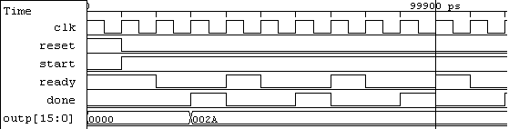
Timing diagram for the minimal FSMD.
In certain cases, input registering might be desired. This intent can be made explicit by copying input port data to an internal register. For the case of the eda algorithm, a new localvar, a would be introduced to perform the copy as a <= mov in1;. The VHDL counterpart is given as a_1_next <= in1;, making this data available through register a_1_reg in the following cycle. For register r, signal r_next represents the value that is available at the register input, and r_reg the stored data in the register.
7.2.1 Communication with embedded memories
Array objects can be synthesized to block RAMs in contemporary FPGAs. These embedded memories support fully synchronous read and write operations. A requirement for asynchronous read mandates the use of memory residing in distributed LUT storage.
In BASIL, the load and store primitives are used for describing read and write memory access. We will assume a RAM memory model with write enable, and separate data input (din) and output (dout) sharing a common address port (rwaddr). To control access to such block, a set of four non-trivial signals is needed: mem_we, a write enable signal, and the corresponding signals for addressing, data input and output.
store is the simpler operation of the two. It requires raising mem_we in a given single-cycle state so that data are stored in memory and made available in the subsequent state/machine cycle.
Synchronous load requires the introduction of a waitstate register. This register assists in devising a dual-cycle state for performing the load. Fig. fsmd-loadstore-vhdl illustrates the implementation of a load operation. During the first cycle of STATE_1 the memory block is addressed. In the second cycle, the requested data are made available through mem_dout and are assigned to register mysignal. This data can be read from mysignal_reg during STATE_2.
Wait-state-based communication for loading data from a block RAM.
when STATE_1 =>
  mem_addr <= index;
  waitstate_next <= not (waitstate_reg);
  if (waitstate_reg = '1') then
    mysignal_next <= mem_dout;
    next_state <= STATE_2;
  else
    next_state <= STATE_1;
  end if;
when STATE_2 =>
  ...
7.2.2 Hierarchical FSMDs
Our extended FSMD concept allows for hierarchical FSMDs defining entire systems with calling and callee CDFGs. A two-state protocol can be used to describe a proper communication between such FSMDs. The first state is considered as the preparation state for the communication, while the latter state actually comprises an evaluation superstate where the entire computation applied by the callee FSMD is effectively hidden.
The calling FSMD performs computations where new values are assigned to *_next signals and registered values are read from *_reg signals. To avoid the problem of multiple signal drivers, callee procedure instances produce *_eval data outputs that can then be connected to register inputs by hardwiring to the *_next signal.
Fig. fsmd-pcall-vhdl illustrates a procedure call to an integer square root evaluation procedure. This procedure uses one input and one output std_logic_vector operands, both considered to represent integer values. Thus, a procedure call of the form (m) <= isqrt(x); is implemented by the given code segment.
State-superstate-based communication of a caller and callee procedure instance in VHDL.
when STATE_1 =>
  isqrt_start <= '1';
  next_state <= SUPERSTATE_2;
when SUPERSTATE_2 =>
  if ((isqrt_ready = '1') and (isqrt_start = '0')) then
    m_next <= m_eval;
    next_state <= STATE_3;
  else
    next_state <= SUPERSTATE_2;
  end if;
when STATE_3 =>
...
isqrt_0 : entity WORK.isqrt(fsmd)
  port map (
    clk, reset,
    isqrt_start, x_reg, m_eval,
    isqrt_done, isqrt_ready
  );
STATE_1 sets up the callee instance. The following state is a superstate where control is transferred to the component instance of the callee. When the callee instance terminates its computation, the ready signal is raised. Since the start signal of the callee is kept low, the generated output data can be transferred to the m register via its m_next input port. Control then is handed over to state STATE_3.
The callee instance follows the established FSMD interface, reading x_reg data and producing an exact integer square root in m_eval. Multiple copies of a given callee are supported by versioning of the component instances.
7.2.3 Steaming ports
ANSI C is the archetypical example of a general-purpose imperative language that does not support streaming primitives, i.e. it is not possible for someone to express and process streams solely based on the semantics of such language.
Streaming suits applications with absence of control flow. In a prime factorization algorithm (pfactor), a streaming output can be used, outp, to produce successive factors. The streaming port is accessed based on valid. Thus, outp is accessed periodically in context of basic block BB4 as shown in fsmd-pfactor-nac.
NAC code for a prime factorization algorithm involving output streaming.
procedure pfactor (in u16 x, out u16 outp) {
  localvar u16 i, n, t0;
BB1:
  n <= mov x;
  i <= ldc 2;
  BB2 <= jmpun;
BB2:
  BB3, BB_EXIT <= jmple i, n;
BB3:
  t0 <= rem n, i;
  BB4, BB5 <= jmpeq t0, 0;
BB4:
  n <= div n, i;
  outp <= mov i;
  BB3 <= jmpun;
BB5:
  i <= add i, 1;
  BB2 <= jmpun;
BB_EXIT:
  nop;
}
7.2.4 Operation chaining
Operation chaining assigns dependent SSA operations to a single control step. Simple means for selective operation chaining involve merging successive ASAP states. In successive states, intermediate registers are eliminated by wiring assignments to *_next signals and reusing them in the subsequent chained computation, instead of reading from the stored *_reg value. To avoid excessive critical paths, a heuristic is defined for disallowing flow-dependent multiple occurrences of expensive operators in the same newly defined state.
In Fig. fsmd-eda-chaining states S_1_3 to S_1_5 comprise intermediate computations in a merged S_1_1 state.
2D euclidean distance approximation algorithm (eda) without chained computations.
...
when S_1_3 =>
  t3_next <= "000"&x_reg(15 downto 3);
  t4_next <= "0"&y_reg(15 downto 1);
  next_state <= S_1_4;
when S_1_4 =>
  t5_next <= x_reg - t3_reg;
  next_state <= S_1_5;
when S_1_5 =>
  t6_next <= t4_reg + t5_reg;
  next_state <= S_1_6;
2D euclidean distance approximation algorithm (eda) with chained computations.
when S_1_1 =>
  ...
  t3_next <= "000"&x_next(15 downto 3);
  t4_next <= "0"&y_next(15 downto 1);
  t5_next <= x_next - t3_next;
  t6_next <= t4_next + t5_next;
  ...
8 The HercuLeS GUI
8.1 Introduction
The HercuLeS 1.0 (2013a) distribution includes a graphical user interface (GUI) for allowing user-friendly access to HercuLeS HLS without the burden of coping with command-line syntax. The main purpose of the GUI is for the user to control code generation, simulation and synthesis options via an intuitive scheme. The user sets various options for the overall process from within the GUI (by interacting with checkbuttons, radiobuttons, entries, text widgets etc) in order for a shell script to be generated which will steer these tasks transparently. For running the generated script, a minimal Unix bash script environment is expected. On Windows, the MinGW and msys distributions are suggested. On Linux, the required facilities are natively supported in almost any distributions, including Ubuntu Linux 12.04 LTS.
To summarize, the HercuLeS GUI performs the following tasks:
- Allow the user to set various options and to load a C or NAC program file for processing
- Optionally, load a configuration file (which automatically sets all necessary options)
- Generate the HercuLeS run script
- Execute the HercuLeS run script
- View results from within an included results browser.
The HercuLeS GUI can be accessed by double-clicking on the icon of the hercules.exe executable, or by command-line invocation as follows:
from within the top-level directory of your HercuLeS installation.
The HercuLeS GUI executable is available on both 32-bit Windows and 32-bit Linux.
8.2 Overview
When executing hercules.exe, a splashscreen appears for a few seconds, as shown in Fig. hercules-gui-splashscreen.

The HercuLeS GUI splashscreen.
After the lapse of a few seconds, the basic configuration screen of HercuLeS is visible. A nominal view of the GUI is shown in Fig. hercules-gui-basicscreen. The GUI consists of the following:
- a dropdown menu with the File, General, Action, Configuration, Theme (on the left side) and Help (on the right side) submenus.
- A set of basic framed controls for setting the simulator (Simulator), waveform generation settings (Output waveform format), simulation and synthesis options (Simulation and synthesis options) and miscellaneous options (Miscellaneous options).
- A notebook for controlling high-level synthesis settings in detail, which consists of four tabs: General, Optimizations, Operation scheduling and Code generation.
- The read-only console where the standard output is logged in real-time in order to examine the progress of the current run.
- A set of buttons: Run HercuLeS, Results browser, Clear generated files, Clear console (on the left), and Exit (on the right). Except Run HercuLeS, all other buttons are disabled at startup.

The initial HercuLeS GUI screen immediately after invocation.
A major element of the HercuLeS GUI which is not readily visible is the Results browser. This element is activated after a successful run of generating and executing a HercuLeS run script for a specific C or NAC translation unit.
It should be noted that context-specific balloon help is available for most visible controls. This kind of help of accessible simply by mouse hovering over the corresponding GUI element.
8.3 Quick-start guide
The fastest and simplest way to use the HercuLeS GUI is a four-step process. Using this process, the user is able to perform C simulation, VHDL simulation and logic synthesis on the generated C and VHDL representation of a specified C or NAC program file.
The process is as follows:
- From the File menu either load a C application (Load C program file) or a NAC application (Load NAC program file).
- From the File menu, press Load HercuLeS configuration and choose default.config.
- From the Action menu, press Run HercuLeS (or press the always visible Run HercuLeS button near the bottom-left corner of the basic screen layout.
- When enabled, press Results browser from the bottom-left corner of the basic screen layout. This will invoke the results browser.
Fig. hercules-gui-quickstart depicts graphically the proposed four-step process for quickly setting up and processing a program file with HercuLeS.

The four-step quick-start process for using the HercuLeS GUI.
8.4 The GUI in detail
8.4.1 Dropdown menus
8.4.1.1 File submenu
From left to right, the first dropdown menu is File which covers basic file opening/loading, viewing and editing operations. It is shown in Fig. hercules-gui-ddmenu-file.
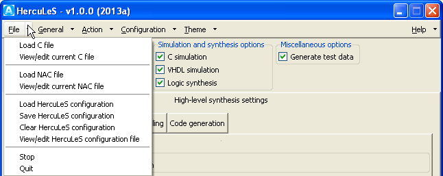
Dropdown menu for file loading, viewing and editing.
HercuLeS can process either C or NAC single-translation-unit programs. The first set of options deal with handling C program files. Load C file allows for loading a C file for processing with a .c extension. To view and optionally edit the file, the selection View/edit current C file is used. To view or edit a C file, the C file should be already loaded, otherwise a relevant popup message box will appear to prompt for loading a C file.
The builtin editor/viewer for C files (the same goes for NAC and configuration files) allows to save your changes but not to rename the loaded file. Fig. hercules-gui-fileviewer shows a C program file in the file editor/viewer.
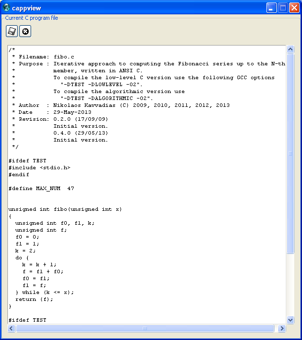
C file editor/viewer in the HercuLeS GUI.
In order to load NAC files, Load NAC file is used. NAC files are expected to have either an .nac, .asm, or .s extensions, since NAC (N-Address Code) programs are essentially written in a form of typed-assembly language. Upon selection, the corresponding NAC file is automatically loaded for processing.To view and optionally edit the file, the selection View/edit current NAC file is used. To view or edit a NAC file, the NAC file should be already loaded, otherwise a relevant popup message box will appear to prompt for loading a NAC file.
The builtin editor/viewer for NAC files is similar to the one used for editing and viewing ANSI/ISO C program files.
HercuLeS configuration files allow the user to supply a full set of configuration options to HercuLeS without interfering with the GUI elements. As a result, loading a translation unit for processing and configuring HercuLeS has a much smaller turnaround time. Configuration files have the .config suffix; their format is explained in the corresponding section. The option Load HercuLeS configuration allows for loading a configuration file. The HercuLeS distribution comes with at least one predefined configuration file, named default.config.
Configuration files can be saved under different names. This is a useful feature for the user, and enables the backup and storage of an existing configuration, e.g. one setup interactively by the user. Save HercuLeS configuration popups the corresponding dialog for storing the current configuration as a configuration file.
To clear the loaded configuration, Clear HercuLeS configuration is used. The result is that only minimal settings will be loaded, for instance no HDL simulation and logic synthesis will be enabled on this setting.
To view and optionally edit the configuration file, the selection View/edit HercuLeS configuration file is used. To view or edit a configuration file, the configuration file should be already loaded, otherwise a relevant popup message box will appear to prompt for loading a configuration file.
The options Stop and Quit allow for ending the current run of HercuLeS abruptly, and to exit the environment, correspondingly. These options are equivalent to pressing <Control-C> and <Control-Q> from the keyboard during a HercuLeS session.
8.4.1.2 General submenu
The second dropdown menu is General which is a placeholder for options that can be applied in general to all tools that are invoked by HercuLeS. Specifically, the nac2cdfg translator from NAC to Graphviz CDFGs and the cdfg2hdl backend (HDL code generator from Graphviz CDFGs) are affected by the options of this dropdown menu. This menu is shown in Fig. hercules-gui-ddmenu-general.
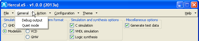
Dropdown menu for general options.
Debug output enables the emission of additional diagnostic information to the standard output during a HercuLeS script run. This includes printouts of the contents of various internal data structures of both nac2cdfg and cdfg2hdl.
Quiet mode disables the emission to the standard output of both any additional diagnostic information as well as other informative messages during a HercuLeS script run. When enabling this mode, only indications of the start and end of a HercuLeS script run are generated and depicted in the read-only console.
8.4.1.3 Action submenu
The third dropdown menu is Action which provides several controls for generating and executing a HercuLeS run script, as well as displaying the generated result files in a custom browser, optimized for this purpose.
Fig. hercules-gui-ddmenu-action illustrates the corresponding submenu.
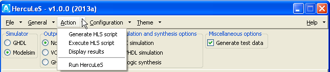
Dropdown menu for script action options.
Generate HLS script should be used when the user has already setup either a C or NAC program file and has loaded or interactively specified a configuration. By clicking this menubutton, the HercuLeS script for the specified application is generated. The generated script is a bash shell script which follows the naminb convention hercules-app.sh, where app is the name of the C or NAC program file. app should be the same to the name of the top-level procedure in the specified translation unit.
Execute HLS script can be used for forcing the execution of the generated HercuLeS run script. All actions that are performed by the HercuLeS run script (or HLS script) are logged in real-time to the read-only console. Script execution start is indicated by the following message:
while when script execution completes, the following message is generated to wrap up the contents of standard output:
Following the completion of HercuLeS run script execution, Display results can be used to load the results browser. The results browser provides a tree-view of each generated item (file) and allows for easy viewing of the contents of this file, when applicable in graphical form.
The Run HercuLeS menubutton when selected applies all the three previous actions in sequence:
- Generate HLS script
- Execute HLS script
- Display results
No further user intervention is required for generating the script for driving the high-level synthesis process, executing the script, invoking all necessary external tools (such as the host C compiler, HDL simulators and the Xilinx ISE/XST logic synthesis tool), and loading the results browser when HLS has completed.
8.4.1.4 Configuration submenu
The fourth dropdown menu is Configuration which provides layouts with entries and choices for configuring external tools and to provide information on the host system setup.
Fig. hercules-gui-ddmenu-config illustrates the corresponding submenu.

Dropdown menu for environment and external tool configuration options.
HercuLeS environment and tools provides access to Environment configuration options for the HercuLeS setup (HercuLeS installation path), host compiler options, HercuLeS frontend options and source optimizer options. Fig. hercules-gui-ddmenu-config-env shows the default environment configuration options.
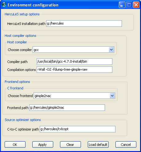
Layout for specifying environment configuration options.
As the host compiler, either gcc or llvm can be used. This choice affects the host compiler (either GCC or LLVM) used for test data generation and backend C code simulation. Within the same set of options, the path to the /bin directory of the host compiler can be set (currently this is left unused; the host compiler is assumed to be in the system PATH environmental variable). Further, a string specifying the compilation options passed to the host compiler is specified in Compilation options, however this is only used with the gimple2nac HercuLeS frontend, since it affects only this case.
Frontend options provide a choice among to distinct ANSI C frontends, gimple2nac which uses GIMPLE intermediate dumps generated by gcc in order to extract the corresponding NAC representation of the application, and irc2nac which uses a custom translator from IR-C (a low-level C subset, generated by a port of the LANCE compiler) to NAC. The Frontend path entry should direct to the directory where the executable of the corresponding frontend is placed.
Source optimizer options specifies the top-level directory of the included C-to-C source optimizer provided with the HercuLeS distribution. This optimizer is named txlcopt and is nominally placed in the /txlcopt subdirectory of the HercuLeS distribution.
At the bottom of the Environment configuration layout, several buttons are located. The OK button is used to close this dialog without further changes. Apply stores the current settings of the environment configuration. Clear removes all user-specified settings. Load default reinstantiates the predefined defaults which are specified in the hercules.ini initialization file. Cancel allows to cancel the current operation.
This five-button configuration is used for all configuration layouts that are accessible through the Configuration dropdown menu.
Xilinx XST/ISE environment provides access to Xilinx XST/ISE configuration options for the the Xilinx XST/ISE external logic synthesis tool. Fig. hercules-gui-ddmenu-config-xst shows the default Xilinx XST/ISE configuration options.

Layout for specifying Xilinx XST/ISE configuration options.
Path to Xilinx ISE is an entry for setting the path to the ISE directory of the user's Xilinx ISE/XST installation. A specific FPGA architecture and device should be specified in order to be picked up by the synthesis process. Thus, the user should specify a meaningful combination of an FPGA architecture (Choose FPGA device family) and FPGA device (Choose FPGA device part). The following combinations are the ones that are supported in HercuLeS v1.0.0 (2013a):
- spartan3 with xc3s200-ft256-4
- virtex4 with xc4vlx25-ff668-10
- virtex6 with xc6vlx75t-ff484-1
The corresponding dropdown widget elements allow for the user to add other choices as well. The dropdown lists can be updated to show all entries by selecting Load default. This issue appears to be as a bug in the GRIDPLUS widget set which is used for the configuration layouts.
External tools provides access to External tools configuration options for third-party external tools e.g. for image visualization. An example of a default layout for these options is shown in Fig. hercules-gui-ddmenu-config-xtools.

Layout for specifying third-party tool configuration options.
Currently, these options specify the path and name of the image viewer. In addition, the path to the Graphviz distribution (which should be installed in the user's machine) as well as the name of the Graphviz processor (dot) and the preferred Graphviz file viewer (one option is dotty, which is bundled with all Graphviz distributions; other choices are also offered by other third parties).
HercuLeS comes on Windows with a free for-commercial-use image viewer named Imagine. The proper local path to Imagine is thus automatically specified. However, the user can bypass this setting by providing the details for the image viewer of preference.
8.4.1.5 Theme submenu
The fifth dropdown menu is Theme which provides simple access to all available themes of the host execution platform. Fig. hercules-gui-ddmenu-theme illustrates the corresponding submenu as it appears in a typical Windows XP installation using ActiveTcl 8.5.14.

Dropdown menu for changing the GUI theme.
In this example, the following themes are accessible:
- xpnative
- clam
- alt
- classic
- default
- winnative.
For a Linux installation, the available set of themes could be possibly much different. In all cases, all available themes will be accessible through this dropdown submenu.
The following set of figures illustrate the appearance of the basic GUI screen using the different themes on Windows.

Basic GUI screen using the xpnative theme on Windows.

Basic GUI screen using the clam theme on Windows.

Basic GUI screen using the alt theme on Windows.

Basic GUI screen using the classic theme on Windows.
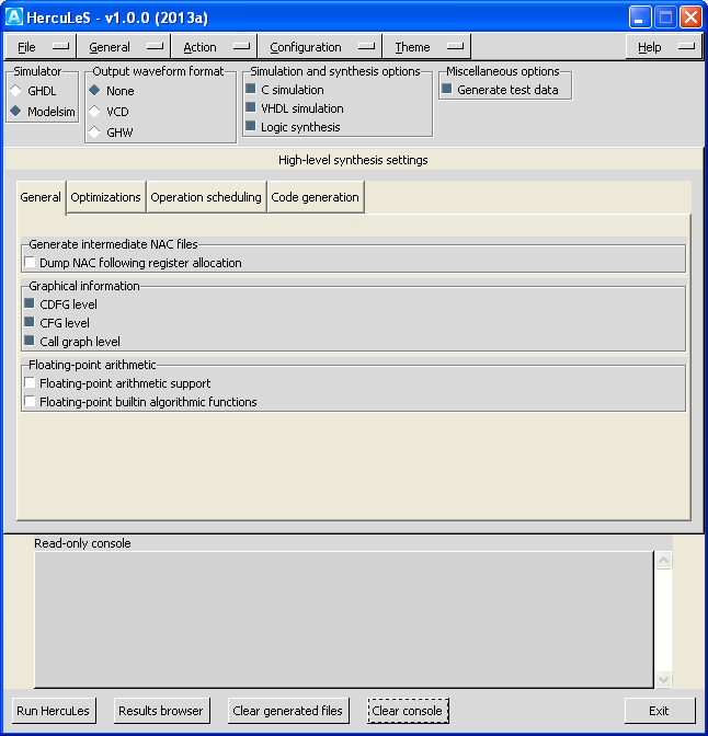
Basic GUI screen using the default theme on Windows.
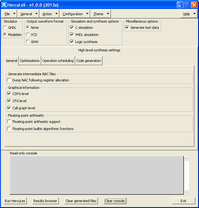
Basic GUI screen using the winnative theme on Windows.
8.4.1.6 Help submenu
The sixth and last dropdown menu is Help from which the PDF and HTML version of the HercuLeS reference manual can be accessed, by pressing the HTML manual and PDF manual menubuttons respectively. When invoked, an external HTML browser and PDF viewer (based on the default settings of the host system) will be called for viewing. When About is pressed the following message is generated, for version 1.0.0 (2013a) of the HercuLeS distribution.
HercuLeS
Ajax Compilers <info@ajaxcompilers.com>
Developed by Nikolaos Kavvadias
<nkavvadias@ajaxcompilers.com>
Version 1.0.0 (29-Jun-2013)}
Fig. hercules-gui-ddmenu-help illustrates the corresponding submenu.
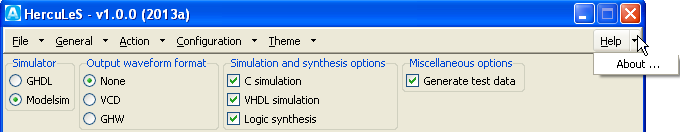
Dropdown menu for accessing help and about information.
8.4.2 Framed controls
A set of basic controls are always visible as part of the basic screen layout of the HercuLeS GUI. Fig. hercules-gui-framedcontrols illustrates all the available basic framed controls.
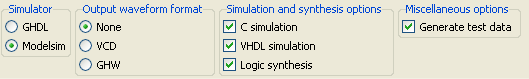
Controls always visible in the basic screen layout.
8.4.2.1 Simulator control
The Simulator control provides a choice between different HDL simulators. Currently, only VHDL simulation is needed since only VHDL RTL code is generated as a result of the high-level synthesis process. The available choices for simulators are GHDL (for the GHDL simulator) and Modelsim (for Mentor Modelsim). It is expected that both of these simulators (or at least the one that is intended for use) is already installed on the host system and its executables directory is declared within the PATH environmental variable.
8.4.2.2 Output waveform format control
The Output waveform format control allows to choose between three choices for generating or not waveform data from the HDL simulation:
- None: do not generate any kind of waveform data
- VCD: generate waveform as Value Change Dump (VCD)
- GHW: generate GHDL Waveform (GHW) data
VCD and GHW are both supported by recent versions of the GTKwave waveform viewer.
8.4.2.3 Simulation and synthesis options control
The Simulation and synthesis options control is a set of checkbuttons to enable or disable the generation of corresponding entries in the HercuLeS run script for the following:
- running a C simulation using the C backend files generated by a NAC-to-C decompilation process (C simulation)
- running an HDL simulation using either specified simulator (VHDL simulation)
- invoke the Xilinx ISE/XST logic synthesis tool (Logic synthesis)
8.4.2.4 Miscellaneous options
The Miscellaneous options control groups all remaining controls. Currently only Generate test data is available. When enabled, this checkbutton enables using the host C compiler for generating reference test input/output data for the application under processing.
8.4.3 Notebook controls
In order to control in detail the available high-level synthesis settings, a notebook (currently consisting of four tabs) is always accessible from the basic screen layout of the HercuLeS GUI.
These tabs organize General, Optimizations, Operation scheduling and Code generation controls into corresponding categories.
8.4.3.1 General tab
From left to right, the first notebook tab is General which covers general file emission options. It is shown in Fig. hercules-gui-nb-general and consists of three option groups.
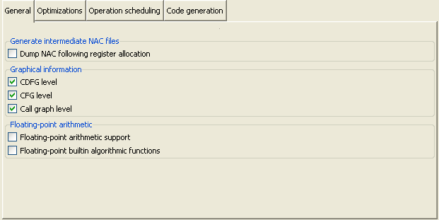
Notebook tab for general high-level synthesis settings.
The first option group, Generate intermediate NAC files, can be used to enable intermediate dumps after various stages of the HLS compilation process. Currently on printing intermediate NAC files for each procedure following register allocation can be specified.
The second option group, Graphical information, can be used for enabling and disabling of the emission of graphical information at the CDFG (Control-Data Flow Graph), CFG (Control-Flow Graph) and Call graph level. A CDFG illustates control and data dependencies between the statements in a NAC procedure. A CFG illustrates only the control dependencies at basic block granularity in a procedure. A call graph depicts the call graph structure of the entire translation unit.
The third option group, Floating-point arithmetic, provides control settings for the support of floating-point arithmetic (Floating-point arithmetic support). Another checkbutton, Floating-point builtin algorithmic functions enables the rewriting of NAC programs so that transcendental standard C library functions (such as calls to sin() and atan()) to be replaced by non-synthesizable implementations provided by proposed extensions to the VHDL-2008 floating-point arithmetic package.
8.4.3.2 Optimizations tab
The second notebook tab is Optimizations which covers optimization-specific options. All depicted optimizations regard external optimizers that are bundled within the HercuLeS distributions for transforming C, NAC, or Graphviz representations. The notebook view is shown in Fig. hercules-gui-nb-opt and consists of three option groups.
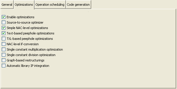
Notebook tab for optimization settings.
This tab basically groups a set of checkbuttons for enabling or disabling specific optimizations. The first checkbutton, Enable optimizations, enables or disables the entire group of the following checkbuttons. The supported optimizations are as follows:
- Source-to-source optimizer: The txlcopt optimizer which is a collection of C-to-C transformation passes developed in the TXL functional programming language. txlcopt supports arithmetic-oriented, loop-based and generic restructuring transformations.
- Simple NAC-level optimizations: TXL transformations written for NAC programs.
- Text-based peephole optimizations A collection of optimizations on NAC code applied with the help of the copt text-based peephole optimizer.
- NAC-level if-conversion: If conversion transformation applied on NAC programs. This transformation cannot be guaranteed to always produce valid code since it is purely syntax-driven and should only be used with care.
- Single constant multiplication optimization: Automatic replacement of single constant multiplications by optimized multiplierless routines at the NAC level.
- Single constant division optimization: Automatic replacement of single constant divisions by optimized divisionless routines at the NAC level.
- Graph-based restructurings: A set of gvpr transformations for use on Graphviz graphs. gvpr provides a scripting language interface for manipulating graphs expressed in the Graphviz language similar to awk.
- Automatic library IP integration: This option enables the automatic replacement the uses of specific VHDL operators (e.g. variable multiplications and divisions) by optimized library IP. HercuLeS takes care of all the required integration and interconnection effort associated with this task.
8.4.3.3 Operation scheduling tab
The third notebook tab is Operation scheduling which covers operation scheduling and memory synthesis options. Overall, this tab is dedicated for the setting of options that control aspects of the generated HDL architectures. A typical tab view is shown in Fig. hercules-gui-nb-arch and consists of two option groups.
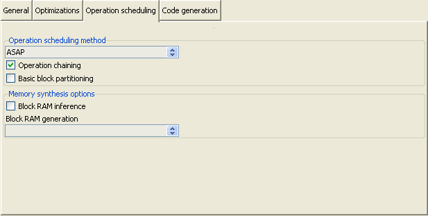
Notebook tab for architecture-specific high-level synthesis settings.
The first option group, Operation scheduling method, can be used for selecting one of the provided schedulers for the task of operation scheduling. Currently Sequential and ASAP scheduling are supported. Sequential schedules one operation per FSMD state. ASAP is a form of unconstrained scheduling and allows for mutually-independent operations to be bundled within the same FSMD control step (state).
The Operation chaining checkbutton enables a heuristic that allows to collapse multiple dependent operations within the same FSMD control step. In some cases, this technique leads to overcontention of specific FSMD states and subsequently to lower performance (e.g. reduced clock period due to larger combinational path). Basic block partitioning contributes a heuristic so that existing basic blocks are split into smaller ones in order to alleviate for this problem.
The second option group is named Memory synthesis options and is used for controlling the generation of RAM description that support automatic block RAM inference. This mandates the use of synchronous read descriptions. Xilinx block RAM support different read schemes. The corresponding combobox, Block RAM generation enables the user to select among two different schemes, Read-first and Read-through. Both schemes are explained in the Xilinx XAPP463 application note on block RAM usage.
8.4.3.4 Code generation tab
The fourth and last notebook tab is Code generation which covers options that affect code generation in HercuLeS. A view of this tab is shown in Fig. hercules-gui-nb-cgen and consists of three option groups regarding backend code generation, SSA (Static Single Assignment) and register allocation.
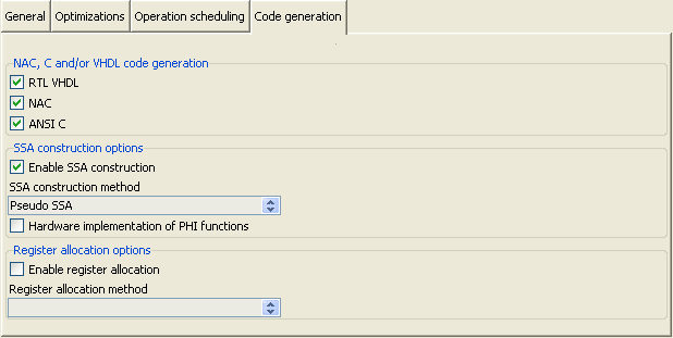
Notebook tab for code generation settings.
The first option group, NAC, C and VHDL code generation, provides checkbuttons for controlling the emission of NAC, backend ANSI C and RTL VHDL code. NAC and ANSI C backend code are generated by the nac2cdfg tool, while RTL VHDL is generated by the graph-based cdfg2hdl backend tool of HercuLeS.
This is followed by SSA construction options, a control set for fine-tuning the generated intermediate representation form by nac2cdfg. Generating SSA form is mandatory for non-sequential operation scheduling like the ASAP scheme. Apart from the Enable SSA construction checkbutton, a combobox permits to choose among two different methods for IR construction, classic minimal SSA which can be generated by using the Aycock-Horspool technique and Pseudo SSA which is a form of intrablock variable numbering. The latter is much faster than the former, however not a true SSA scheme, since the single definition point property of SSA form is not sustained at interblock scope. Another checkbutton, Hardware implementation of PHI functions allows for a direct mapping of SSA form (which involves so-called PHI functions which are join points for variable definitions from different control paths) to hardware. The default choice is to first convert SSA form out-of-SSA. In this case, PHI functions are removed and move operations must be placed to construct all necessary variable copies.
Register allocation options is a set of controls for setting whether register allocation is to be applied. When register allocation is disabled, simply its temporary variable is translated to a hardware register. To perform register allocation the Enable register allocation checkbutton must be selected. Currently only linear-scan register allocation (Linear scan) can be selected from the corresponding register allocation method combobox.
8.4.4 Action buttons
A set of five action buttons, Run HercuLeS, Results browser, Clear generated files, Clear console (on the left), and Exit (on the right) is visible near the bottom of the basic screen layout. Fig. hercules-gui-basicscreen-actions illustrates the corresponding controls.

Action buttons situated near the bottom of the basic screen layout.
The actions performed by Run HercuLeS and Results browser have been already described. Clear generated files deletes all generated result files from the working directory of the loaded C or NAC program file. Clear console deletes all information that has been emitted in the read-only console. Exit forces the HercuLeS GUI to close. It should be noted that Results browser, Clear generated files and Clear console are only enabled following the execution of a HercuLeS script.
8.4.5 Results browser
The HercuLeS GUI comes with a results browser which is invoked after the execution of a HercuLeS run script has completed. Fig. hercules-gui-resbrowser illustrates an example view of the results browser layout.

The HercuLeS GUI results browser.
On the left side, the results browser uses a tree viewing GUI element. This tree viewer loads a file named hlsrestree.tcl from the application's current (working) directory. This file provides an automatically-generated GRIDPLUS tree widget to enable browsing of generated files from the high-level synthesis process.
An example hlsrestree.tcl automatically generated for a Fibonacci series (fibo) computation application is shown below:
gpset .treebrowser.hlstree {
  {/PRGM + "Program: fibo" :folder_blue-22}
  {/PRGM/RPTS + "Reports" :folder_graph_white-22}
  {/PRGM/RPTS/RESANSIC "ANSI C simulation results" :txt-22}
  {/PRGM/RPTS/RESVHDL "VHDL simulation results" :txt-22}
  {/PRGM/RPTS/RESXST "XST/ISE synthesis report" :txt-22}
  {/PRGM/PROC0 + "Procedure: fibo" :folder_grey-22}
  {/PRGM/PROC0/CDFG + "CDFG: fibo" :folder_red-22}
  {/PRGM/PROC0/CDFG/DOT "Graphviz dot" :dot-22}
  {/PRGM/PROC0/CDFG/PNG "PNG image" :png-22}
  {/PRGM/PROC0/CFG + "CFG: fibo" :folder_orange-22}
  {/PRGM/PROC0/CFG/DOT "Graphviz dot" :dot-22}
  {/PRGM/PROC0/CFG/PNG "PNG image" :png-22}
  {/PRGM/PROC0/NAC + "NAC representation" :folder_green-22}
  {/PRGM/PROC0/NAC/FINAL "Optimized NAC : fibo.nac" :nac-22}
  {/PRGM/PROC0/NAC/POSTFE "NAC: fibo_ssa.nac" :nac-22}
  {/PRGM/PROC0/ANSIC + "ANSI C representation" :folder_olive-22}
  {/PRGM/PROC0/ANSIC/FINAL "C backend code for fibo: fibo_nac.c" :ansic-22}
  {/PRGM/PROC0/VHDL + "Generated VHDL files for fibo" :folder_magenta-22}
  {/PRGM/PROC0/VHDL/RTL "RTL design for fibo" :vhdl-22}
  {/PRGM/PROC0/VHDL/CDTPKG "Compound data structures package for fibo" :vhdl-22}
  {/PRGM/CG + "Call graph: fibo" :folder_yellow-22}
  {/PRGM/CG/DOT "Graphviz dot" :dot-22}
  {/PRGM/CG/PNG "PNG image" :png-22}
  {/PRGM/GLOBAL + "Global miscellaneous files for fibo" :folder_white-22}
  {/PRGM/GLOBAL/HERCSH "Generated HercuLeS bash script for fibo" :bash-22}
  {/PRGM/GLOBAL/PROCNMS "Procedure names in fibo" :txt-22}
  {/PRGM/GLOBAL/BUILTINS "Black box procedures in fibo" :txt-22}
  {/PRGM/GLOBAL/TESTDATA "Reference I/O data for fibo" :txt-22}
  {/PRGM/GLOBAL/MAINC "C driver code for fibo: main.c" :ansic-22}
  {/PRGM/GLOBAL/MAINH "C header code for fibo: main.h" :ansic_header-22}
  {/PRGM/GLOBAL/MK "Makefile for builting C backend code: ansic.mk" :makefile-22}
  {/PRGM/GLOBAL/RSIMDO ".do script for VHDL simulation using Modelsim" :txt-22}
  {/PRGM/GLOBAL/RSIMSH "Bash script for running the VHDL simulation" :bash-22}
  {/PRGM/GLOBAL/XSTSH "Bash script for running logic synthesis with Xilinx XST/ISE" :bash-22}
  {/PRGM/VHDL + "Global VHDL files for fibo" :folder_cyan-22}
  {/PRGM/VHDL/PKG "Global package for fibo" :vhdl-22}
  {/PRGM/VHDL/TB "Testbench for fibo" :vhdl-22}
}
On the right side, the user can view either a textual or a graphical representation (the latter when appropriate) of the requested information. Currently, the Graphical view and Statistics views are left unused. It should be noted that when requesting a PNG visualization of a graph (e.g. a CDFG, CFG or call graph), an external image viewer is accessed, the name of and the path to which can be defined via means of the initialization file or the external tools configuration layout.
The following table summarizes all automatically generated files that are accessible from the results browser environment. The name of the current application is app.
| Path to tree widget | Description |
| /PRGM | Top-level folder for app. |
| /PRGM/REPORTS | Reports folder. |
/PRGM/REPORTS/DEBUG /PRGM/REPORTS/RESANSIC /PRGM/REPORTS/RESVHDL /PRGM/REPORTS/RESXST |
Debug dump. ANSI C simulation results. VHDL simulation results. XST/ISE synthesis report. |
| /PRGM/PROC$i | Top-level folder for procedure proc. |
| /PRGM/PROC$i/CDFG | CDFG folder for proc. |
/PRGM/PROC$i/CDFG/DOT /PRGM/PROC$i/CDFG/PNG |
Graphviz dot representation for the CDFG. PNG image visualization of the Graphviz CDFG. |
| /PRGM/PROC$i/CFG | CFG folder for proc. |
/PRGM/PROC$i/CFG/DOT /PRGM/PROC$i/CFG/PNG |
Graphviz dot representation for the CFG. PNG image visualization for the CFG. |
| /PRGM/PROC$i/NAC | Folder for the NAC representation of proc. |
/PRGM/PROC$i/NAC/FINAL /PRGM/PROC$i/NAC/POSTFE /PRGM/PROC$i/NAC/RA |
Optimized NAC for proc. NAC following frontend processing for proc. NAC following register allocation for proc. |
| /PRGM/PROC$i/ANSIC | Folder for the ANSI C representation of proc. |
| /PRGM/PROC$i/ANSIC/FINAL | C backend code for proc. |
| /PRGM/PROC$i/VHDL | Folder for generated VHDL files of proc. |
/PRGM/PROC$i/VHDL/RTL /PRGM/PROC$i/VHDL/CDTPKG |
RTL design for proc. Compound data structures package for proc. |
| /PRGM/CG | Call graph for app. |
/PRGM/CG/DOT /PRGM/CG/PNG |
Graphviz dot representation for the call graph. PNG image visualization for the call graph. |
| /PRGM/GLOBAL | Global miscellaneous files for app. |
/PRGM/GLOBAL/HERCSH /PRGM/GLOBAL/PROCNMS /PRGM/GLOBAL/BUILTINS /PRGM/GLOBAL/TESTDATA /PRGM/GLOBAL/MAINC /PRGM/GLOBAL/MAINH /PRGM/GLOBAL/MK /PRGM/GLOBAL/RSIMMK /PRGM/GLOBAL/RSIMDO /PRGM/GLOBAL/RSIMSH /PRGM/GLOBAL/XSTSH |
Generated HercuLeS bash script for app. Procedure names in app. Black box procedures in app. Reference I/O data for app. C driver code for app. C header code for app. Makefile for builting C backend code. Makefile for VHDL simulation using GHDL. .do script for VHDL simulation using Modelsim. Bash script for running the VHDL simulation. Bash script for running logic synthesis. |
| /PRGM/VHDL | Folder for global VHDL files of app. |
/PRGM/VHDL/PKG /PRGM/VHDL/TB |
Global package for app. Testbench for app. |
8.5 Configuration files
HercuLeS supports user-defined configuration files for fast loading of high-level synthesis settings. A configuration file is expected to have the .config suffix. The supplied options are organized into four distinct categories, common (options that are common across all tools), nac2cdfg (passed to the HercuLeS nac2cdfg tool), cdfg2hdl (passed to the HercuLeS cdfg2hdl tool) and more where all miscellaneous options are defined. For the first three categories, these options represent command-line switches. The last category, more, defines options that are intentionally similar to command-line switches but are however passed to the HercuLeS GUI directly for controlling HercuLeS run script generation.
The general structure of a configuration file is shown below:
start-common
<options>
end-common

start-nac2cdfg
<options>
end-nac2cdfg

start-cdfg2hdl
<options>
end-cdfg2hdl

start-more
<options>
end-more
An example of a typical configuration file invoking C backend file simulation, VHDL simulation and XST/ISE synthesis is shown below:
start-common
end-common

start-nac2cdfg
-force-data-types
-ssa
-pseudo-ssa
-emit-nac
-emit-ansic
-emit-cfg
-emit-cg
end-nac2cdfg

start-cdfg2hdl
-sched-asap
-ieee
-vhd2vl
-mpint
-mti
end-cdfg2hdl

start-more
-optimizations
-nacsopt
-nacpeep
-chain
-rsim
-csim
-datagen
-synth
-emit-cdfg
end-more
The list of command-line switches that are passed to the HercuLeS GUI is as follows:
- -optimizations:
- Enable optimizations.
- -srcopt:
- Source-to-source optimizer.
- -nacsopt:
- Simple NAC-level optimizations.
- -nacpeep:
- Text-based peephole optimizations.
- -txlpeep:
- TXL-based peephole optimizations.
- -nacifconv:
- NAC-level if-conversion.
- -kmul:
- Single constant multiplication optimization.
- -kdiv:
- Single constant division optimization.
- -gvpropt:
- Graph-based restructurings applied on Graphviz CDFG graphs.
- -ipopt:
- Automatic library IP integration.
- -bbpart:
- Enable basic block partitioning.
- -emit-vhdl:
- Emit RTL VHDL code.
- -xst-script:
- Generate a script for driving Xilinx XST/ISE logic synthesis.
- -rsim:
- Enable VHDL simulation.
- -csim:
- Enable backend C code simulation.
- -datagen:
- Generate reference input/output data for the loaded application.
- -emit-cdfg:
- Generate Graphviz CDFGs and their PNG visualizations for the application.
- -synth:
- Enable logic synthesis.
8.6 Initialization file
During startup, the HercuLeS GUI automatically loads a predefined initialization file, named hercules.ini. This .ini file assigns all required environmental and internal variables for the proper setup of HercuLeS.
The initialization file is an ASCII text file comprising of a set of entries of the following form:
where variable is the name of the environmental or internal use variable to be set and rhs-string is the string value that is assigned to it.
The following table provides a brief summary of the variables that can be defined in initialization files.
| Name | Description |
| hlstop | Top-level installation directory for HercuLeS. |
| compiler_name | Name of the host C compiler. |
| compiler_path | Path to the executables' directory of the host C compiler. |
| compiler_opts | Command-line options to pass to the host C compiler for generating GIMPLE dumps (only for gcc and gimple2nac). |
| cfe_name | Name of the C frontend for compiling to NAC. |
| cfe_path | Path to the C frontend executable. |
| srcopt_path | Path to the C-to-C optimizer. |
| xilinx_ise_path | Path to the Xilinx ISE directory. |
| fpga_arch | FPGA architecture to be used for logic synthesis. |
| fpga_part | FPGA device to be used for logic synthesis. |
| graphviz_path | Path to the Graphviz installation. |
| dotproc_name | Name of the Graphviz dot processor (default: dot). |
| dotviewer_name | Name of the Graphviz file viewer (default: dotty). |
| imgviewer_name | Name of the image viewer executable. |
| imgviewer_path | Path to the image viewer executables' directory. |
| pdfviewer_name | Name of the PDF viewer executable. |
| pdfviewer_path | Path to the PDF viewer executables' directory. |
| htmlviewer_name | Name of the HTML viewer executable. |
| htmlviewer_path | Path to the HTML viewer executables' directory. |
An example initialization file is shown below:
hlstop="g:/hercules"
compiler_name="gcc"
compiler_path="/usr/local/bin/gcc-4.7.0-install/bin"
compiler_opts="-Wall -O2 -fdump-tree-gimple-raw"
cfe_name="gimple2nac"
cfe_path="g:/hercules/gimple2nac"
srcopt_path="g:/hercules/txlcopt"
xilinx_ise_path="c:/Xilinx/12.3/ISE_DS/ISE"
fpga_arch="virtex6"
fpga_part="xc6vlx75t-ff484-1"
graphviz_path="c:/CompSci/Graphviz2.28"
imgviewer_path="g:/hercules/thirdparty/Imagine"
imgviewer_name="Imagine"
dotproc_name="dot"
dotviewer_name="dotty"
pdfviewer_path="c:/Program\ Files/Adobe/Reader\ 10.0/Reader"
pdfviewer_name="AcroRd32"
htmlviewer_path="c:/Documents\ and\ Settings/nkavvadias/Local\ Settings/Application\ Data/Google/Chrome/Application"
htmlviewer_name="chrome"